
General about DC motors
Separate field excitation DC motors are still sometimes used for driving machines at variable speed. These motors are very easy to miniaturize, and essential for very low powers and low voltages.
They are also particularly suitable, up to high power levels (several megawatts), for speed variation with simple, uncomplicated electronic technologies for high performance levels (variation range commonly used from 1 to 100).
They are however less rugged than asynchronous motors and much more expensive, in terms of both hardware and maintenance costs, as they require regular servicing of the commutator and the brushes.
Construction of DC motor //

A DC motor is composed of the following main parts:
Field coil or stator
This is a non-moving part of the magnetic circuit on which a winding is wound in order to produce a magnetic field. The electro-magnet that is created has a cylindrical cavity between its poles.
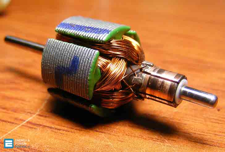
Armature or rotor
This is a cylinder of magnetic laminations that are insulated from one another and perpendicular to the axis of the cylinder. The armature is a moving part that rotates round its axis, and is separated from the field coil by an air gap. Conductors are evenly distributed around its outer surface.
Commutator and brushes
The commutator is integral with the armature. The brushes are fixed. They rub against the commutator and thus supply power to the armature conductors.
Operating principle
When the field coil is energized, it creates a magnetic field (excitation flux) in the air gap, in the direction of the radii of the armature. This magnetic field “enters” the armature from the North pole side of the field coil and “exits” the armature from the South pole side of the field coil.
The conductors located under the other pole are subject to a force of the same intensity in the opposite direction. The two forces create a torque which causes the motor armature to rotate (see Figure 1).

When the motor armature is powered by a DC or rectified voltage supply U, it produces back emf E whose value is:
E = U – RI
where RI represents the ohmic voltage drop in the armature.
E = k ω Φ
Where:
- k is a constant specific to the motor
- ω is the angular speed
- Φ is the flux
This equation shows that at constant excitation the back emf E (proportional to ω) is an image of the speed.
The torque is linked to the field coil flux and the current in the armature by the equation:
T = k Φ I
If the flux is reduced, the torque decreases.
There are two methods for increasing the speed //
1. Either increase the back emf E, and thus the supply voltage at constant excitation: this is known as “constant torque” operation.
2. Or decrease the excitation flux, and thus the excitation current, while keeping the supply voltage constant: this is known as “reduced flux” or “constant power” operation. This operation requires the torque to decrease as the speed increases (see Figure 2 below). However, for high reduced flux ratios this operation requires specially adapted motors (mechanically and electrically) to overcome switching problems.

The operation of this type of device (DC motor) is reversible //
If the load opposes the rotation movement (the load is said to be resistive), the device provides a torque and operates as a motor.
If the load is such that it tends to make the device rotate (the load is said to be driving) or it opposes the slow-down (stopping phase of a load with a certain inertia), the device provides electrical energy and operates as a generator.
Various types of DC motor
Parallel excitation (separate or shunt)
The coils, armature and field coil are connected in parallel or supplied via two sources with different voltages in order to adapt to the characteristics of the machine (e.g.: armature voltage 400 volts and field coil voltage 180 volts).
The direction of rotation is reversed by inverting one or other of the windings, generally by inverting the armature voltage due to the much lower time constants. Most bidirectional speed drives for DC motors operate in this way.

Series wound
The design of this motor is similar to that of the separate field excitation motor. The field coil is connected in series to the armature coil, hence its name. The direction of rotation can be reversed by inverting the polarities of the armature or the field coil.
Compound wound (series-parallel excitation)
This technology combines the qualities of the series wound motor and the shunt wound motor. This motor has two windings per field coil pole. One is connected in parallel with the armature. A low current (low in relation to the working current) flows through it. The other is connected in series.
It is an added flux motor if the ampere turns of the two windings add their effects. Otherwise it is a negative flux motor. But this particular mounting method is very rarely used as it leads to unstable operation with high loads.

Open DC motor – School project (VIDEO)
Here we have an open DC motor with permanent magnet for the field. An old armature from a faulty hedge trimmer was used. As it was for a school project The following topics had to be covered.
- Chemical energy – We used a lead acid battery
- Kinetic energy – We got the armature rotating
- Noise – We got audio from the speaker
- Heating – We got some heating in the armature, and commutator bars
- Light – We made a special LED driven via coil
- Magnetic – We established that the armature won’t rotate without the magnet underneath.
Cant see this video? Click here to watch it on Youtube.
Reference // Cahier technique no. 207 – Electric motors – Schneider Electric


So nice
wow..thanks for the article this helped a lot …for my exam
Hi Sir Edvard,
Good day.
Thank you for your article, It is really helpful. Can I use this article as a reference? Hope you can come back to me sir.
Warm regards,
Romar
This article has been written totally technically and I have gain lots of knowledge about dc motors from this article.
good
The article is well written. However, I agree with Mr. Derek. You can see that the machine is not a DC Machine as commutator is missing! Edvard, please replace with a picture of DC machine.
Picture Construction of DC Machine.
I believe it is a picture of an Asychronous Alternating Current Induction Motor not a DC Machine>
Check out
https://www.google.com.au/search?q=cutaway+view+direct+current+machines&safe=active&biw=1920&bih=912&source=lnms&tbm=isch&sa=X&ved=0CAYQ_AUoAWoVChMIkbWGmKaVxgIVTaa8Ch0WnAB8&dpr=1&safe=on&gws_rd=ssl#gws_rd=ssl&imgrc=FswJhyu3dA9B8M%253A%3BeThnzADAlnmJTM%3Bhttp%253A%252F%252F1.bp.blogspot.com%252F-ycaWcg-XSP8%252FVWuEnA12EjI%252FAAAAAAAABO4%252FVN8YR5fDjj8%252Fs640%252FDC%25252BMotor%25252BCutaway.jpg%3Bhttp%253A%252F%252Feeecommunity.blogspot.com%252F2015_05_01_archive.html%3B500%3B425
You’re right Derek, it was a wrong picture. I fixed it. Thank you!
Seriously speaking hats off to you. you have great knowledge of electrical engineering & you have make me feel proud as an electrical engineer. keep it up man.