Distribution substations purpose
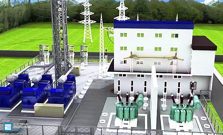
Distribution substations serve a wide range of private and public customers in distributing electric power. They can be shareholder, cooperatively, privately, and government owned. All substations contain power transformers and the voltage-regulating apparatus required for converting the high incoming sub-transmission voltages to lower primary system voltages and maintaining them within specified voltage tolerances.

Those voltages, typically 11 to 15 kV, are then sent to distribution transformers and load substations for serving regional and local customers.
Substations serve many purposes, including connecting generators, transmission or distribution lines, and loads to each other and generally stepping higher voltages down to lower voltages to meet specific customer requirements. They can also interconnect and switch alternative sources of power and control system voltage and power flow. Power factor can be corrected and overvoltage can be regulated by substations.
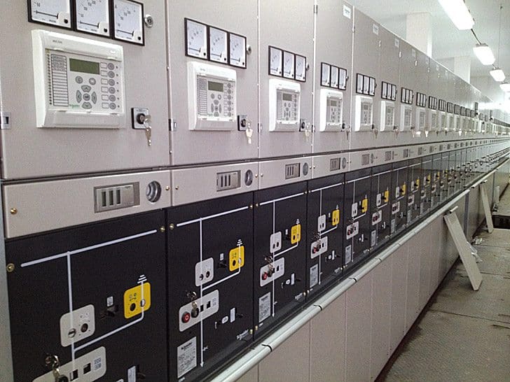
In addition, instruments in substations measure power, detect faults, and monitor and record system operational information.


The basic equipment in distribution substations includes: transformers, circuit breakers, disconnect switches, bus bars, shunt reactors, power factor correction capacitors, lightning arresters, instrumentation, control devices, and other protective apparatus related to the specific functions in the power station.
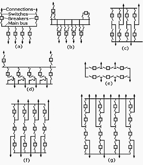
Circuit breakers and other switching equipment in a substation can be organized to separate a bus, part of a transformer, or a control device from other equipment. The common system switching arrangements are shown in the one-line diagrams in Figure 1.
In these diagrams connections are indicated by arrowheads, switches by offset lines, and circuit breakers by boxes.
The single-bus switching system in Figure 1a is bus protected by the circuit breakers on the incoming and outgoing lines. The double-bus system in Figure 1b has two main buses, but only one is normally in operation; the other is a reserve bus. The ring bus in Figure 1e has the bus arranged in a loop with breakers placed so that the opening of one breaker does not interrupt the power through the substation.


For more details about each arrangement of the switching devices – refer here.
Typical distribution substations
A typical distribution system consists of //
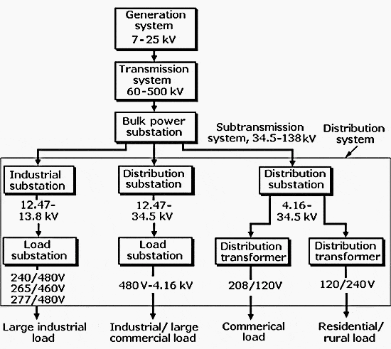
- Sub-transmission circuits, which carry voltages ranging from 12.47 to 245 kV (of these, 69, 115, and 138 kV are most common) for delivering electrical energy to the various distribution substations.
- Three-phase primary circuits or feeders, which typically operate in the range of 4.16 to 34.5 kV (11 to 15 kV being most common) for supplying the load in designated areas.
- Distribution transformers rated from 10 to 2500 kVA, installed on poles, on above-ground pads, or in underground vaults near customers. These transformers convert primary voltage to useful voltages for practical applications.
- Secondary circuits at useful voltage levels, which carry the energy from the distribution transformers along highways, streets, or rights-of-way. These can be either single-phase or three-phase lines.
- Service drops and service laterals, which deliver energy from the secondary circuits to the user’s service entrance equipment.


Power is switched from the substation transformers as shown in Figure 1 above to separate distribution buses. In some systems the buses distribute power to two separate sets of distribution lines at two different voltages.
Smaller transformers connected to the bus step the power down to a standard single-phase line voltage of about 7.2 kV for residential and rural loads, while power from larger transformers can leave in another direction at the higher three-phase voltages to serve large industrial and commercial loads.
Electrical substation: how does it work? (VIDEO)
Substations are bit like the crossroads of the electrical network. In this video, learn more about their crucial role in the transportation and distribution of electricity. This video also describes the two types of substation technologies: conventional air-insulated substations (AIS) and gas-insulated substations (GIS).
Reference // Handbook Of Electrical Design Details – Neil Sclater, John E. Traister (Get it from Amazon)


Sir,I want detail design of 400/220/33 KV GIS substation
Sir the videos are good.
Hi Edward topic about what is electrical distribustion system is very useful for beginners great job. One thing I suggest you about the topic of grid energy meter concept how it’s works ? Please post in the future
Thank you for such insightful articles. I have a team of Engineers that I share your regular updates with. This is definitely assisting with speeding up their exposure to this industry.
You’re welcome Nishan. Thank you.
Sir, I Whole heartedly appreciate your work in sharing the technical knowledge with engineers who are on the way to experience the real world. I having done my engineering in Electrical & Electronics engineering, and for past 4 years working as Sales & marketing engineer. I’m very much interested to become an entrepreneur and thus looking the platform on which it is better to start with, keeping in mind the long term reliability. Could you please help me out in guiding the right way to start.
sir i want details design and all calculation of 132/33 kv substation
I must say that you are doing a good work pls keep it up