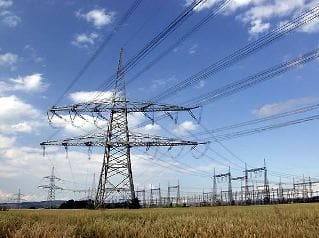
Subtransmission systems are those circuits that supply distribution substations. Several different subtransmission systems can supply distribution substations. Common subtransmission voltages include 34.5, 69, 115, and 138 kV. Higher voltage subtransmission lines can carry more power with less losses over greater distances.
Distribution circuits are occasionally supplied by high-voltage transmission lines such as 230 kV; such high voltages make for expensive high-side equipment in a substation. Subtransmission circuits are normally supplied by bulk transmission lines at subtransmission substations.
For some utilities, one transmission system serves as both the subtransmission function (feeding distribution substations) and the transmission function (distributing power from bulk generators). There is much crossover in functionality and voltage. One utility may have a 23-kV subtransmission system supplying 4-kV distribution substations.
Another utility right next door may have a 34.5-kV distribution system fed by a 138- kV subtransmission system. And within utilities, one can find a variety of different voltage combinations.

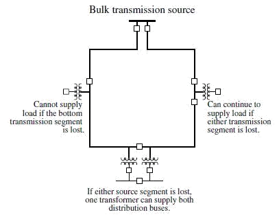
Of all of the subtransmission circuit arrangements, a radial configuration is the simplest and least expensive (see Figure 1.15). But radial circuits provide the most unreliable supply; a fault on the subtransmission circuit can force an interruption of several distribution substations and service to many customers. A variety of redundant subtransmission circuits are available, including dual circuits and looped or meshed circuits (see Figure 1.16).
The design (and evolution) of subtransmission configurations depends on how the circuit developed, where the load is needed now and in the future, what the distribution circuit voltages are, where bulk transmission is available, where rights-of-way are available, and, of course, economic factors.
Most subtransmission circuits are overhead. Many are built right along roads and streets just like distribution lines. Some — especially higher voltage subtransmission circuits — use a private right-of-way such as bulk transmission lines use. Some new subtransmission lines are put underground, as development of solid-insulation cables has made costs more reasonable.
Lower voltage subtransmission lines (69, 34.5, and 23 kV) tend to be designed and operated as are distribution lines, with radial or simple loop arrangements, using wood-pole construction along roads, with reclosers and regulators, often without a shield wire, and with time-overcurrent protection.
Higher voltage transmission lines (115, 138, and 230 kV) tend to be designed and operated like bulk transmission lines, with loop or mesh arrangements, tower configurations on a private right-of-way, a shield wire or wires for lightning protection, and directional or pilot-wire relaying from two ends. Generators may or may not interface at the subtransmission level (which can affect protection practices).

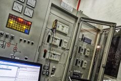
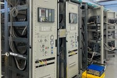


See national grid for more detail.
Theory for 5 g At sea wind solar machinery and lines used in transference of waves through lines reflecting through land bouncing off pylons fir a non dangerous way of 5g subrtransmussion and pylon usage in sea and land. Lines in sea and land through wave reflection not interfering with shipping radar. Lines in sky elevated through solar.