Power, voltage & alternating current
In a DC circuit, the power is equal to the voltage times the current, or P=V×I. This is also true in an AC circuit when the alternating current and voltage are in phase. That is, when the circuit is resistive.
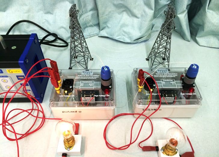
But, if the AC circuit contains reactance, there is a power component associated with the magnetic and/or electric fields. The power associated with these fields is not consumed as it is in a resistance, but rather stored and then discharged as the alternating electric current / voltage goes through its cycle.
This leads to another definition:
Apparent power =
Real or True power (linked to resistance) +
Reactive power (linked to inductance or capacitance)
A related concept is that of power factor, which is defined as a magnitude of P divided by a magnitude of S. In the electric power industry, if the power factor is too low (typically under 0.85) because of the magnitude of the reactive component Q, corrective actions are usually taken.
Using symbols:
S = P + jQ
Real Power
Real power is available to do work and is equal to the value of the resistance multiplied by the square of the current through the resistance. It is measured by a quantity called megawatts (mW) or kilowatts (kW).
P = I2 x R
Reactive Power
Reactive power neither consumes nor supplies energy. The reactive power associated with an inductive reactance is the value of the inductive reactance multiplied by the square of the current through it. The reactive power is measured by a quantity called volt-ampere reactive or VARs.
As the length of a line increases, its inductive reactance increases, and the more capacitive reactive power needed to offset the effect and to maintain adequate voltage:
QL = I2 x XL
The capacitive reactive power QC relates to the establishment of the electric field around a line. There are a number of ways to calculate this value, but the following offer insight into its effects on the transmission system.
QC = 3 x VLN2 / XC or √3 x VLL x IC
Charging current IC is defined as the line to neutral voltage divided by the capacitive reactance:
IC = VLN / XC
If the charging current becomes too large, much of the line’s current carrying capacity may be “eaten up” by charging current.
Sources and sinks of reactive power
This situation sets limits on the length of an overhead line or of a cable that can be operated without installing some intermediate measures to offset the capacitive current. It is useful to visualize the impact of various devices on the reactive power of a power system as follows:
Sources of reactive power which raise voltage:
- Generators
- Capacitors
- Lightly loaded transmission lines due to the capacitive charging effect
Sinks of reactive power which lower voltage:
- Inductors
- Transformers
- Most heavily loaded transmission lines due to the I2×XL effect
- Most customer load (due to the presence of induction motors and the supply to other electric fields)
A synchronous generator can be made to be either a source of reactive power or a sink by using the generator excitation system to vary the level of its DC field voltage.
During peak load conditions generators are usually operated to supply reactive power to the grid. During light load conditions generators may be used to absorb excess reactive power from the grid, especially where there are long transmission lines or cables nearby.
Reference // Understanding electric power systems – An overview of the technology and the marketplace by Jack Casazza and Frank Delea







one small error mW is milliwatt and MW is megawatt. You are out by 10**9.
Could you please upload conceptual pics of topics also,so that we can understand more easily.Thank you…..