
Estimated Study Time: 33 minutes
Gas Insulated Bus Duct Connections
The gas insulated bus duct is used within the GIS bay to interconnect the bus duct from bay to bay or to connect external connections from the GIS bay to overhead lines and transformers. There are two principles of bus ducts: a passive and an active type. The passive type of bus duct is without any moving or switching device in the same gas compartment.
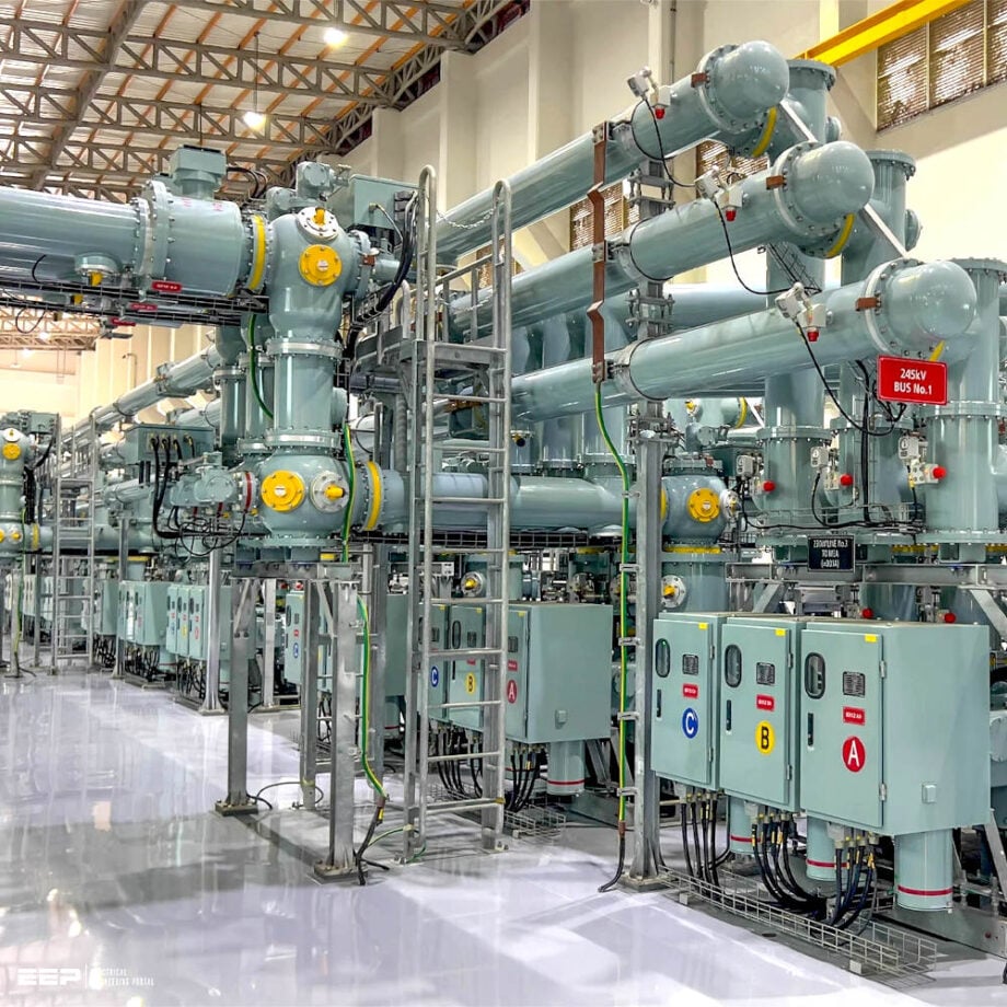 Best Practice for the Installation of Gas Insulated Bus Duct (photo credit: Burns & McDonnell)
The active bus duct has a disconnecting and ground switch included in the bus duct gas compartment. External connections to overhead lines and transformers can reach several kilometers of bus duct length within a substation or a power plant. Bus ducts can be manufactured and assembled in the GIS factory or they may be assembled on site.
This depends mainly on the total transmission length of bus ducts to be assembled on site. The longer the length of the bus duct, the more economical is an on-site assembly. A typical bus duct length for an on-site assembly has some kilometers of single-phase pipe length.
At low voltage ranges the bus duct design is three-phase encapsulation. At voltages above 200 kV the design may be single-phase encapsulated. For voltages of 400 kV and greater any design is single-phase insulated.
On-site testing of long bus duct sections may be limited because of the maximum capacitive load allowed by the test equipment. In such cases sectionizers are required to split the total length in the maximum bus duct length of up to 1 km.
- Bus Ducts in Power Transmission Networks:
- Bus Duct Connection Applications:
- Bus Duct Shipment and Assembly on Site:
- Attachment (PDF) 🔗 Download ‘Best & Common Practice for HV Power Network Construction’
1. Bus Ducts in Power Transmission Networks
1.1 Three-Phase Insulated Bus Duct
The three-phase insulated bus duct is used for the lower voltage range up to 170 kV rated voltage. The limitation of the three-phase insulated design is mainly due to the size of the aluminum casted enclosures.
Also the high short-circuit current levels of the higher voltage classes are giving limits because of the mechanical forces between the conductors.
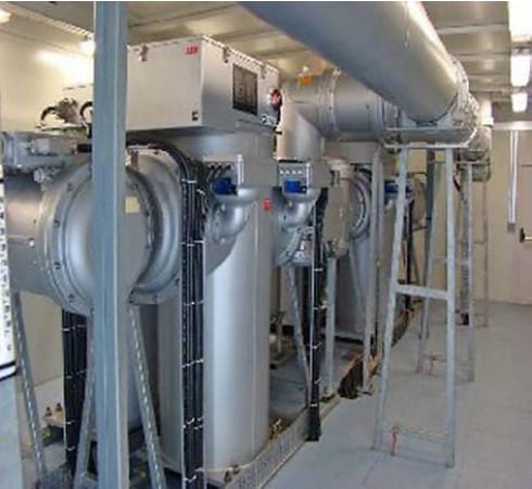
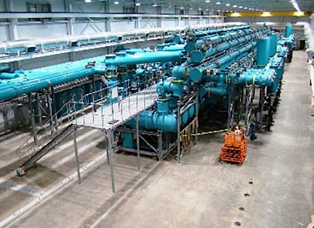
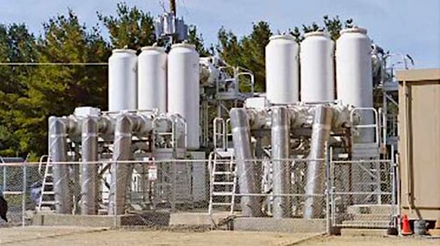
The principle design of three-phase insulated bus ducts has active and passive versions. In the case of the passive design the gas compartment of the bus duct does not include any switching devices (see Figure 1). The bus duct in the upper part of the photo shows the enclosure of three internal conductors connected to the GIS bay.
Figure 1 – Three-phase insulated passive bus duct
The active three-phase encapsulated design of bus ducts includes disconnector switches and ground/earth switches. These disconnect switches connect the bus bar to the GIS bay and the ground/earth switches are used to ground/earth the GIS side when disconnected to the bus duct.
In Figure 2 such an installation is shown on the top of the GIS bays on the left and right of the vertical positioned enclosure for the circuit breaker.
Figure 2 – Three-phase insulated active bus duct
1.2 Single-Phase Insulated Bus Duct
The single-phase insulated bus duct design is the simplest form of GIS. One conical or post type insulator at one end of the bus duct section and a support tool for assembly at the other end is all that is needed to keep the internal conductor pipe in the center of the aluminum pipe.
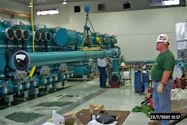
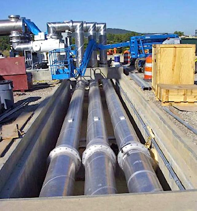
In Figure 3 a section of a single-phase bus duct is shown fixed on a crane during the assembly process.
Figure 3 – Single-phase insulated bus duct on the crane
The advantage of a single-phase bus duct is that, in the case of a short-circuit current the mechanical forces of the current in the conductor and reverse, the induced current in the enclosure is superpositioned in a negative way so that the forces to the insulator are reduced. This allows simple insulators and a high current carrying capability.
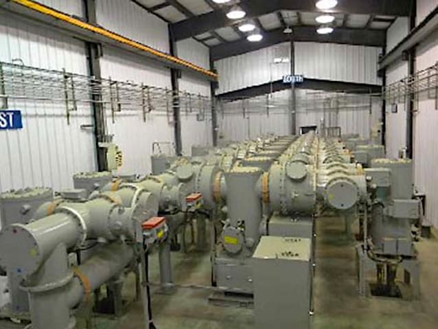
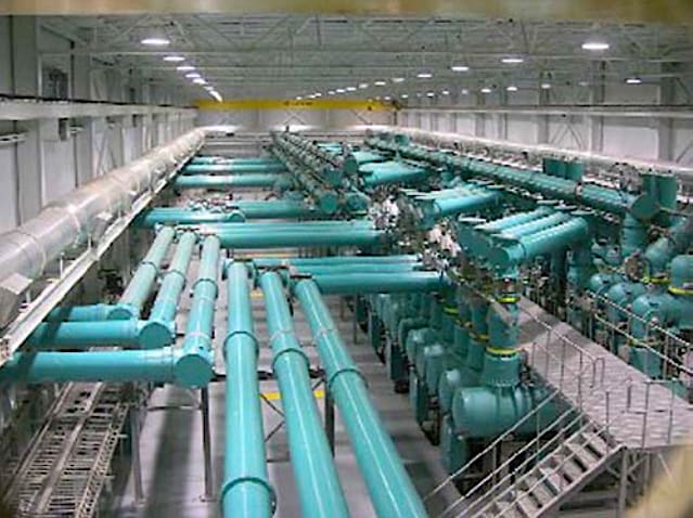
A single-phase passive bus duct is shown in Figure 4.
This reduces the total number of gas compartments. If needed, to reach high flexibility, the gas compartments of the bus duct can be limited to the bay width of the GIS bay by using gastight insulators.
Figure 4 – Single-phase insulated passive bus duct
2. Bus Duct Connection Applications
2.1 Bus Duct to Connect Overhead Lines
Overhead lines need a larger insulation distance between phases and towards earth or ground than those of the GIS because of the lower insulating capability at atmospheric air. Therefore, bus ducts of GIS are used to expand the distances of the GIS bays to those of overhead lines. This is shown in Figure 5.
The single-phase passive bus ducts connect the overhead lines outside the building by using a Z-form. The Z-form has two advantages. First, it allows an expansion to the side of the GIS bay and also a larger distance between phases before leaving the building through a wall passing section.
The Z-form also provides the required movement of thermal expansion by simple angle compensators attached to the Z-form.
Figure 5 – Single-phase insulated bus duct connection to overhead lines outside the GIS building
In Figure 6 the wall passing section is shown. The grounded/earthed enclosure of the bus duct is connected to a grounded/earthed metal plate at the wall passing section to avoid voltage potential differences between the enclosure and the wall.
This avoids arc flashing in this section due to transient overvoltage, for example, at disconnector switching of the GIS.
Figure 6 – Single-phase insulated bus duct to connect overhead lines with wall passing
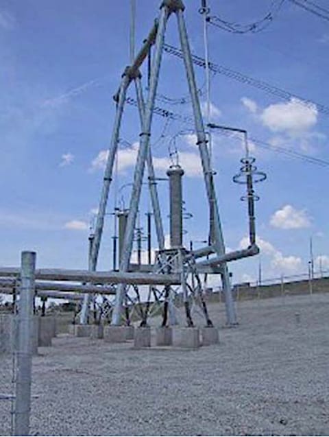
To connect a single-phase bus duct to an overhead line an SF6 gas-to-air bushing is used. At the extended distance between phases the bushings are then directly connected to the wires of the overhead line.
To protect the gas insulated bus duct and the connected GIS from transient overvoltages coming from lightning strokes into the overhead line, surge arresters are used in parallel to the SF6/air bushings, as shown in Figure 7.
Figure 7 – Single-phase insulated bus duct connection to overhead lines with SF6 gas-to-air bushings and surge arresters
2.2 Bus Duct to Connect Circuit Breakers
In some cases bus ducts are used to connect circuit breakers or GIS bays. As this is a connection of SF6 to SF6 insulation only gastight conical insulators are needed to separate the bus duct from the circuit breaker or GIS. This is usually needed if the gas pressure on both sides is different. For mechanical separation, compensators with bellows are used.
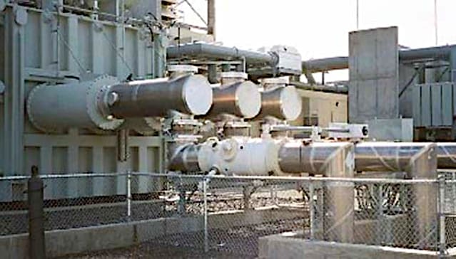
In Figure 8 a single insulated phase bus duct connection to outdoor circuit breakers is shown.
Figure 8 – Single-phase insulated bus duct connection to circuit breakers
2.3 Bus Duct to Connect Power Transformers
For direct connection of bus ducts with transformers a separation of the oil insulation of the transformer and the bus duct is needed. For this a conical insulator is needed to fulfill the oil insulating requirements on one side with the gas insulated requirements on the other side.
To standardize the large variations of direct connection between GIS and transformers, IEC 62271-211 gives recommendations in dimensioning.
This direct connection method is applicable to single- and three-phase arrangements for GIS with rated voltages above 52 kV.
Besides the electrical requirements the mechanical forces and vibrations are also limited between the bus duct and the transformer. For transformer protection of transient overvoltages coming from disconnect operation in the GIS surge arresters are usually used.
In Figure 9 a transformer connection to a bus duct is shown.
Figure 9 – Single-phase insulated bus duct connection to transformers
2.4 Bus Duct to Connect Power Cables
To connect the bus duct with cables two types of cables are used: oil and solid PE insulated cables. The separation of SF6 insulated bus duct and the oil or solid PE insulated cables is made by a special conical insulator to meet the different electrical requirements.
To standardize the big variations of connections, IEC 62271-209 on cable connections for GIS with fluid filled and dry type cable terminations, recommendations of dimensioning are given.
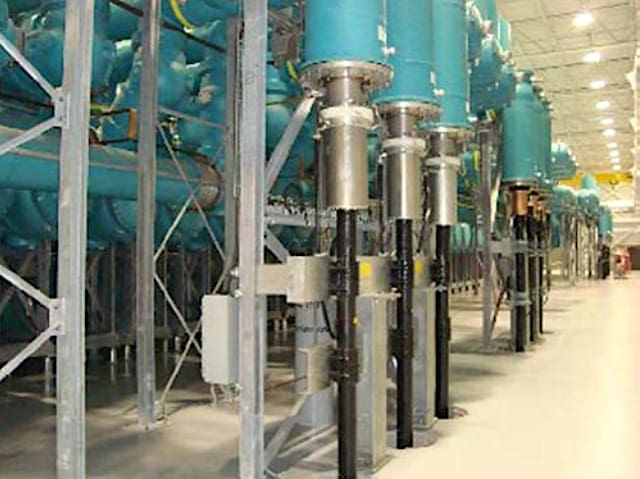
In Figure 10, a single-phase bus duct connection to cables is shown. The vertical enclosure attached to the cable holds the conical insulator between the cable side solid insulation and SF6 gas insulation on the GIS side.
Figure 10 – Single-phase insulated bus duct connection to cables
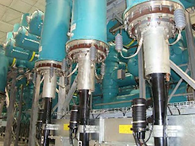
In some cases the cable insulation and the bus duct and GIS insulation need to be separated to avoid sheet currents in the cable shield. For this reason an insulating ring (the brown ring in Figure 11) is required. Varistors bridge the insulating ring at a minimum of three locations in order to avoid flashovers in the case of disconnector switching.
If there were no varistors transient overvoltage coming from the GIS would cause a flashover at the insulated flanges.
See Figure 11.
Figure 11 – Single-phase insulated bus duct connection to cables with overvoltage protection
2.5 Bus Duct to Underpass Overhead Lines
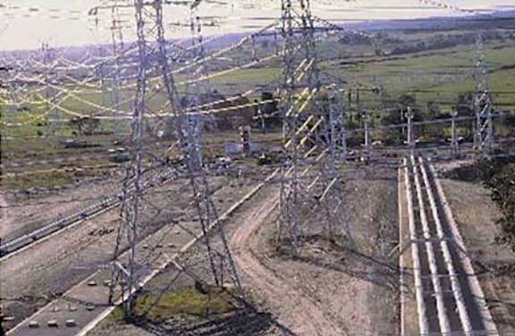
In substations sometimes the overhead lines do not reach the substation at the location where the GIS bay is located. Then it may be necessary to cross under other lines. A bus duct allows a simple solution to underpass overhead lines as shown in Figure 12.
The bus duct in the front of the photo is connected to the GIS bay inside a building and connects three bushings to an overhead line in the background of the photo.
Figure 12 – Single-phase insulated bus duct to underpass overhead lines inside a substation
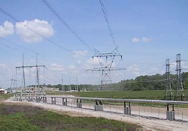
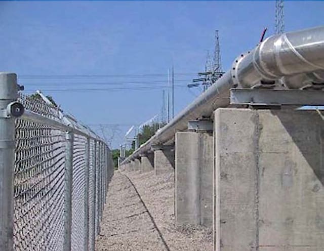
When outside a substation a bus duct needs to be protected with a fence as shown in Figure 13. This access protection is needed to prevent vandalism and general access to unauthorized personnel.
Figure 13 – Single-phase insulated bus duct to underpass overhead lines outside a substation
2.6 Bus Duct Above Ground
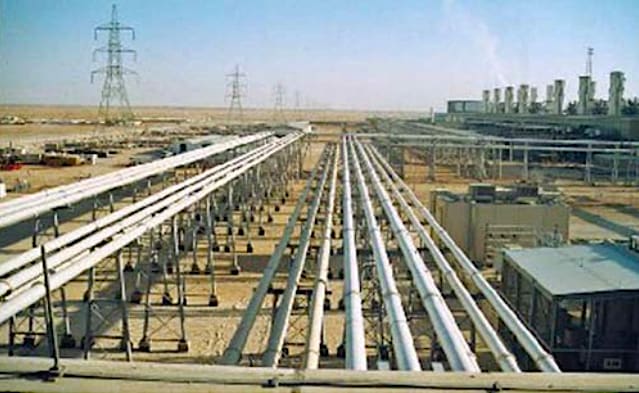
Inside the substations the above ground installation of bus ducts is often used to connect different sections of the substation, to connect the power transformer of the generator, to connect overhead lines, or to connect transformers. Above ground installations use steel structures to carry the enclosure pipes and to allow thermal expansion.
An example of a low steel structure to hold a bus duct is shown in Figure 14. The steel portal holds the weight of the bus duct but allows angle movement of the Z-form arrangement with angle compensation bellows.
Figure 14 – Single-phase insulated bus duct above ground installed at low steel structures
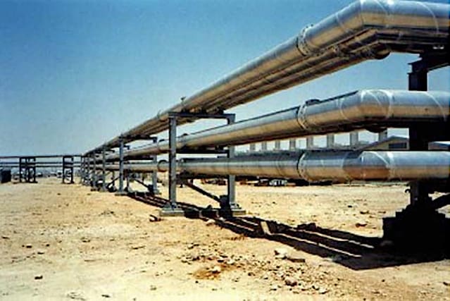
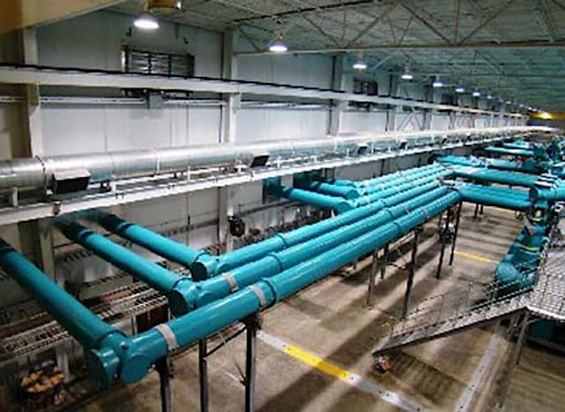
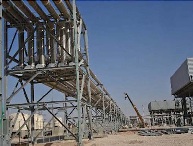
The disadvantage of low steel structures is that the bus duct may hinder the free movement or ground traffic in the substation. If it is required to allow free movement the steel structures are elevated to a height of 4–5 m, as shown in Figure 15.
In this case the bus ducts connect several machine transformers of the gas turbine power plant with the GIS building. The high elevation of the steel structures allows free traffic below. The disadvantage of high elevated steel structures is that a large amount of steel is needed. This can be optimized to a mixture of high elevated steel structures only at locations with ground traffic.
For example, such structures are not needed for substation streets and sections where no free movement is required.
Figure 15 – Single-phase insulated bus duct above ground installation at high steel structures
Then a jump in elevation can be made at the street with traffic, as shown in Figure 15. In addition to straight bus ducts, section angle elements, which are more costly, are needed. This means that a cost optimization is necessary to find the optimum of low and high sections.
Figure 15 – Single-phase insulated bus duct above ground installation with different steel structure heights
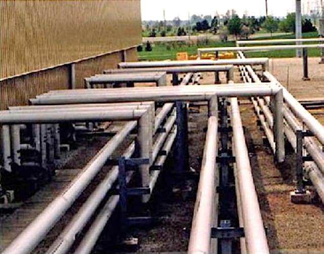
In some application cases, concrete blocks are better to use and more economical than steel structures. In cases of low elevation concrete blocks are used to hold the bus duct.
In Figure 16 the single-phase insulated bus duct is mounted on top of a concrete block using a steel beam and a sliding plate to allow thermal movement of the bus duct.
Figure 16 – Single-phase insulated bus duct above ground installation at concrete blocks
A special application of a bus duct connection underneath overhead lines is shown in Figure 17, where a flooding area is crossed. The concrete blocks are fixed in the dry ring bed, which is temporarily flooded.
The water at flooding times is usually not higher than the concrete blocks. However, the bus duct enclosure pipes are fixed to the steel structure on the top. The fixing will prevent the bus duct from floating in the case where it is under water during a flooding.
The fixing is connected to concrete blocks that are fixed to the ground.
Figure 17 – Single-phase insulated bus duct above ground installation at concrete blocks in a flooding area
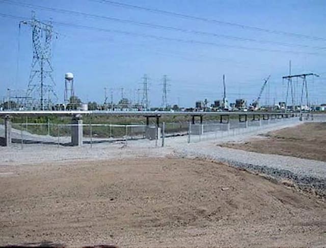
In some cases the location of the GIS bays and the in- and outgoing lines do not match well. Then many line crossings are required. As shown in Figure 18, the bus ducts offer a space saving solution because of the grounded/earthed enclosure potential.
Figure 18 – Single-phase insulated bus duct above ground installation to cross lines
2.7 Bus Duct Trench Laid
In cases where free movement on the ground is required trench-laid bus ducts offer a solution. Trenches can be inside a substation or even outside as they are covered with concrete blocks and, therefore, are not accessible to the public.
The concrete trenches need water treatment to keep the bus duct dry for corrosion protection. The bus duct laid in a trench will have thermal limitations of typical maximum enclosure temperatures of 60 °C when touchable and 70 °C when not touchable according to GIS standards.
Therefore, a thermal calculation is needed for the sections in the trenches that differ from the thermal calculations above ground.
Figure 19 – Single-phase insulated bus duct laid in a trench inside a substation
In Figure 19 a single-phase insulated bus duct is shown laid in a trench inside and in Figure 20 outside a substation.
A trench can be connected to a low tunnel, as shown in Figure 21, where a single-phase insulated bus duct is shown laid in a trench crossing a highway.
Figure 20 – Single-phase insulated bus duct laid in a trench outside a substation
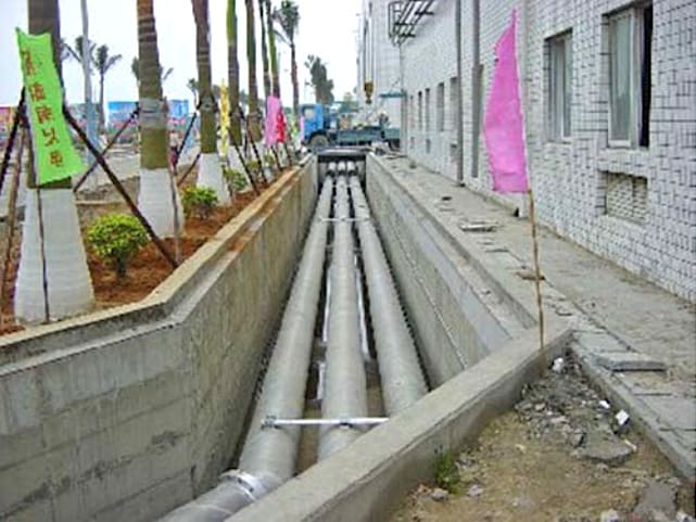
Figure 21 – Single-phase insulated bus duct laid in a trench crossing a highway
2.8 Bus Duct Laid in a Tunnel
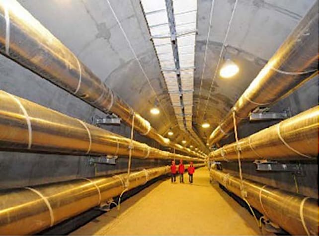
In power plants, mainly in hydro power plants, energy tunnels with bus ducts are often used to connect the generator transformer in the cavern in the dam or cavern at the high voltage side with the substation outside the dam or cavern. Such applications have been built all around the world and usually have one thing in common: a high power transmission capability.
High voltage ratings of 400 kV, 500 kV, and 800 kV are usual. Also, current ratings of 3000 A, 4000 A, or 5000 A are often required.
Figure 22 – Single-phase insulated bus duct double system laid in a horizontal tunnel with vertical angle elements
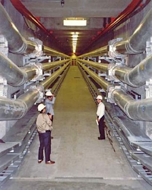
The tunnels are round or squared and usually carry two bus ducts, with three-phase systems of single-phase insulated pipes. In Figure 22 a tunnel with a double system of single-phase insulated bus ducts is shown. To follow the vertical changes of the tunnel angle elements are used.
The voltage level is 500 kV.
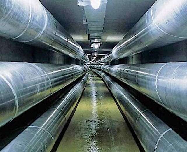
In Figure 23, a tunnel with a double system of single-phase insulated bus ducts is shown. To follow the horizontal bending of the tunnel angle elements are used.
The voltage level is 800 kV.
Figure 23 – Single-phase insulated bus duct double system laid in a horizontal tunnel with horizontal angle elements
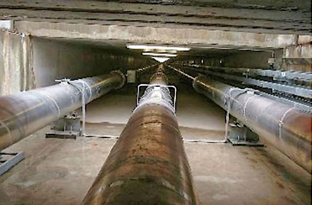
In Figure 24, a tunnel with a double system of single-phase insulated bus ducts is shown. To follow the horizontal bending of the tunnel elastic bending of the aluminum pipes of the bus duct is used.
The voltage is 300 kV.
Figure 24 – Single-phase insulated bus duct double system laid in a horizontal tunnel using elastic bending
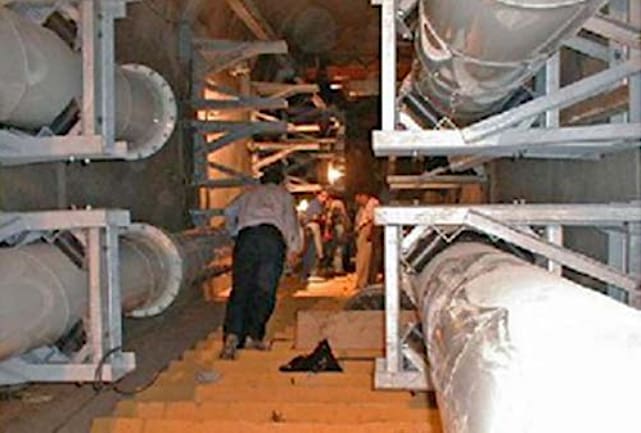
In Figure 25, a tunnel on a slope with a double system of single-phase insulated bus ducts is shown. To follow the slope and to allow thermal movement the bus duct is laid on rollers.
The voltage level is 400 kV.
Figure 25 – Single-phase insulated bus duct double system laid in a tunnel at a slope
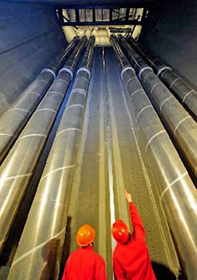
In Figure 26, a vertical shaft is shown, which holds a double system of single-phase insulated bus ducts. The aluminum enclosures are fixed to the shaft walls. The voltage level is 800 kV.
Figure 26 – Single-phase insulated bus duct double system laid in a vertical tunnel
2.9 Bus Duct Directly Buried
Similar to pipelines or cables, the bus duct can also be laid directly buried into the ground. In such a case passive and active outer corrosion protection is needed. Soil coverage to a minimum of 1 m is required to fix the bus duct in the soil. No thermal expansion bellows are needed. The directly buried method can be used inside and outside substations.
For directional changes elastic bending and directly buried angle elements are used.
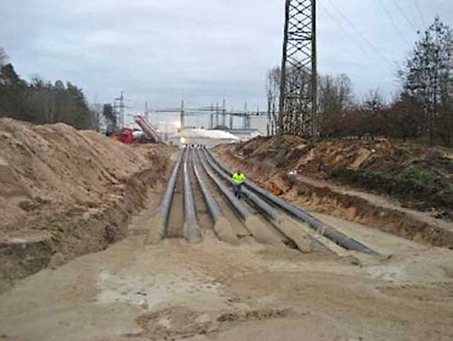
Figure 27 – Single-phase insulated bus duct single system directly buried with a horizontal angle element
In Figure 27 a single-phase insulated bus duct single system is directly buried and includes a horizontal angle element for directional change. The installation is inside a substation to cross existing lines. The voltage level is 145 kV.
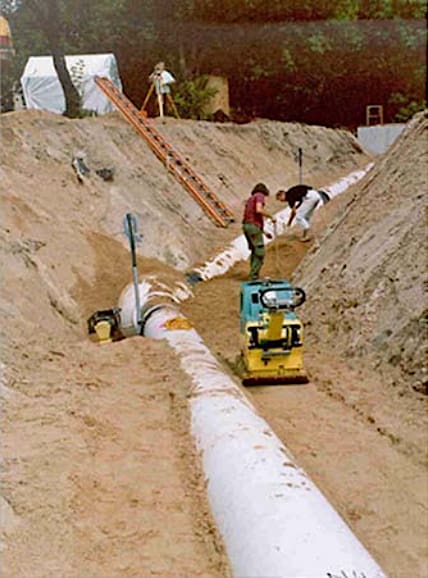
In Figure 28 a single-phase insulated bus duct two-phase loop test circuit shows a vertical angle element. The voltage level is 400 kV.
Figure 28 – Single-phase insulated bus duct two-phase test loop directly buried with a vertical angle element
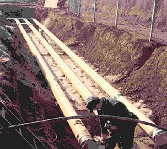
In Figure 29 a single-phase insulated single-phase test section shows a directly buried horizontal and vertical angle element during the laying process. The voltage level is 400 kV.
Figure 29 – Single-phase insulated bus duct single-phase test section directly buried with horizontal and vertical angle elements
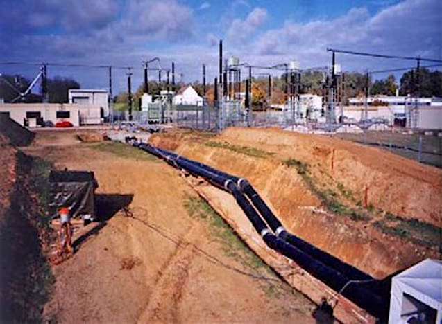
In Figure 30 a single-phase insulated bus duct double system directly buried with elastic bending is shown during the laying process. The voltage level is 400 kV.
Figure 30 – Single-phase insulated bus duct double-phase system directly buried with elastic bending
3. Bus Duct Shipment and Assembly on Site
3.1 Shipment on Site
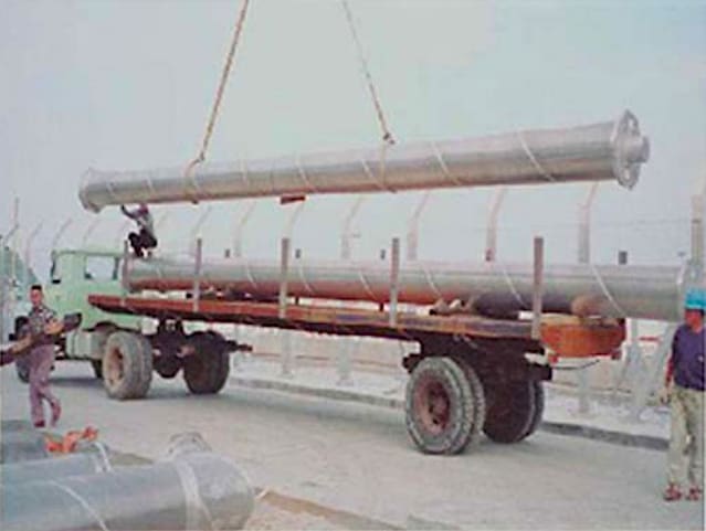
Bus duct sections are shipped to the site on extended bed trucks. Handling on site can be done by crane or forklift trucks. An 18 meter bus section is shown in Figure 31 as it is being unloaded from the truck.
Figure 31 – An 18 meter bus section being unloaded at the site
3.2 Assembly on Site
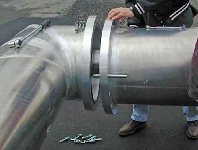
The support structures are placed in position first and roughly leveled. Perfect alignment is not necessary since the GIL is flexible. The GIL shipping sections are moved into place and connected together as shown in Figure 32. A special clean tent is not normally required except for heavy dust conditions.
Flanged or welded joints are done in a similar fashion. The conductor connection is made using a plug and socket connection. It will engage automatically as the two bus duct sections are brought together. Then the enclosure joint is made.
Using this technique for long circuit lengths insures that each joint is complete and leaktight without first evacuating and filling the system with gas.
Figure 32 – Final assembly of a 550 kV field joint. Locating pins are used to align the flanges. Conductor connection is a plug and socket connection with self alignment
4. Attachment (PDF): Best & Common Practice for HV Power Network Construction
Download: Best & Common Practice for HV Power Network Construction (for premium members only):
Source: Gas insulated substations by H. Koch
Related electrical guides & articles


Edvard Csanyi
Hi, I'm an electrical engineer, programmer and founder of EEP - Electrical Engineering Portal. I worked twelve years at Schneider Electric in the position of technical support for low- and medium-voltage projects and the design of busbar trunking systems.I'm highly specialized in the design of LV/MV switchgear and low-voltage, high-power busbar trunking (<6300A) in substations, commercial buildings and industry facilities. I'm also a professional in AutoCAD programming.
Profile: Edvard Csanyi
