
Estimated Study Time: 25 minutes
Substation fence earthing
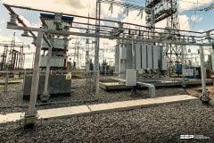
It is recommended that all substations have a perimeter fence surrounding the area where the electrical equipment is housed. As far as security measures go, it is the first line of defense. For the extra layer of protection, competent workers working in the yard can rely on internal fences. To further restrict vehicle access to the substation, fences can be used. For an extra layer of protection, you might utilize many levels of fencing.
 Best practices in earthing of metallic fences in HV outdoor substations
Basic fence standards can be specified using the National Electric Safety Code (NESC) and IEEE/ANSI Standard C2. Minimum requirements for height and material are set out by the NESC. It specifies how far electrical devices on the interior must be from the perimeter of the property.
In addition, shunt reactors, series capacitor banks, and shunts are only a few of the many applications for which the fence requirements are detailed in many IEEE standards and guidelines.
Fences can be constructed from a wide range of materials. The substation yard will be protected from uninvited guests thanks to a fabric barrier. A common material for these fences is chain link fabric attached to metal poles; to deter would-be climbers, three strands of barbed wire are typically strung over the top.
Depending on the laws in your area or country, this barbed wire can be angled either inside or outside the substation.
Two alternative earthing arrangements may be applied to metallic substation fences. These are:
- Independently earthed (or segregated) fence arrangement where the fence is kept electrically isolated from the substation Main Earthing System (MES) (Figure 2), or
- Bonded fence arrangement where the fence is bonded to the substation Main Earthing System (MES) (Figure 3).
Occasionally it may be appropriate to employ both methods on different fence sections at the same site. In this case insulated sections are used to physically link the fences with different earthing arrangements. Where the fence panels are supported by steel posts that are at least 1 m deep in the ground, the posts can be considered as earth electrodes.
Where it is important to provide electrical continuity between adjacent panels (e.g. where overhead lines cross, or run in parallel with the fence or in proximity to magnetic fields), this can be provided by attention to the bolt/fixing connections or by providing a separate continuity conductor which may be buried or supported on the fence.
Ok, let’s dive into the details of earthing metallic fences in HV outdoor substations!
- Independently earthed fences
- Segregation between independently earthed fence and earthing system
- Fences bonded to the substation Main Earthing System (MES)
- Third-party metallic fences
- Insulated fence sections
- Chain link fencing (galvanised or plastic coated)
- Coated fence panels
- Electric security fences
- Anti-climbing precautions
- Risk assessment: Third-party metallic fence near substation
- Attachment (PDF) 🔗 Download ‘Electrical Power Distribution Handbook’
1. Independently earthed fences
If the Main Earthing System (MES) is practically inside the substation perimeter fence, then the fence needs to be earthed separately using rods about 2.4 m long placed at:
- Every corner of the barrier.
- One meter on either side of the place where the high-voltage overhead lines pass through the boundary.
- Other spots, with a minimum distance of 50 m between each rod site.
For further safety, it is recommended to use flexible bonds (minimum CSA 16 mm2 cu or similar) to attach the gates to the posts.
Figure 1 – Independently earthed fence

2. Segregation between independently earthed fence and earthing system
It is important to keep a minimum of 2 meters of clearance above ground between the substation fence and any equipment linked to the Main Earthing System (MES). This is based on the assumption that staff members won’t touch the earthed fence and any earthing-system-connected equipment at the same time.
Considering the placement of substation perimeter electrodes and other factors, it is advisable to keep a comparable distance below ground wherever possible.
Consider mitigation methods, such as insulating paint or barriers that do not compromise security, in cases where the necessary segregation cannot be established.
In Section 10, you can find a formula for calculating the touch potential of a fence.
Figure 2 – Arrangement of separately earthed fence

3. Fences bonded to the substation Main Earthing System (MES)
Use this configuration if the substation’s plant and equipment are within 2 meters of a metal fence or if there are internal fences inside the MES’s domain. Separate but clearly visible connections should be made between the fencing and the MES at the following locations:
- Every corner of the barrier.
- One meter on either side of the place where the high-voltage overhead wiring pass through the fence.
- Extra spots such that there’s no more than 50 m between each connection.
These restrictions are applicable in cases where the substation MES-connected fence is a perimeter fence and the contact potential outside the fence could beyond the safety voltage limits shown in Table 1 below
Table 1 – Permissible touch potentials for typical fault clearance times

Requirement #1
A bare electrode conductor needs to be buried about 1 meter beyond the perimeter fence, at a depth of 0.5 meter. It is important to mitigate the danger of disturbance caused by plowing in agricultural sites.
Requirement #2
To ensure the conductor is fully integrated into the MES, it should be connected to the fence and earthing system at intervals of 50 meters or less.
Requirement #3
Additional safety for animals and people outside the substation can be achieved by chipping the perimeter of the substation. It is necessary to install electrical isolation between two fence systems in areas where substation MES fencing borders independently earthed fencing, creating a potential touch danger.
For information on how to use insulated fence sections to create electrical isolation between fences, see to Section 5: Insulated fence sections.
Figure 3 – Arrangement of bonded fence

4. Third-party metallic fences
Because of the possibility of transmission risk, third parties should not directly connect their metal fences to a substation’s metallic fence. Select one of the following choices to keep the substation electrically isolated from any third-party fences that are present or expected to be within 2 meters of the substation.
Attention! If the third-party fence could serve as a climbing aid, security concerns may make this impossible!
5. Insulated fence sections
Fence sections with insulation can be utilized to separate sections of fencing that are bonded to the substation MES from sections that are earthed independently or connected to third-party fences. Parts that are insulated can be made by:
- Putting up an insulated fence panel that is 2 meters long or more.
- Setting up insulated supports or standoff insulators to hold a metal fence panel that is 2 meters long or longer. In order to keep up with the physical strength of the fence, the insulators must have a voltage withstand capability that is greater than the highest EPR at the site’s perimeter.
You shouldn’t use coated fences (see to Section 7: Coated fence panels) as insulation unless they were made and evaluated for that purpose.
Watch Video – Fence that was NOT grounded properly!
6. Chain link fencing (galvanised or plastic coated)
A proper earthing system for chain link fencing consists of attaching the support posts, straining wires, fence, and any anti-climbing devices to either an independent or bonded electrode system. An electrode run with the fence can facilitate bonding and earthing, making this task much easier.
Instead of depending on the plastic fence coating, which may not be thorough and will likely deteriorate, a grading electrode should be installed to handle any touch potential issues with a plastic coated chain link fence.
Watch Video – Installing chain link fence
7. Coated fence panels
The standard components of coated fence panels are coated galvanized steel mesh panels and galvanized steel support posts. It is important to take measures to prevent damage or erosion of the coating when using them to enclose electrical equipment or a substation, and to earth them properly. Each panel’s metal should preferably be bolted to the support post, and the posts should be earthed by bolts as well.
The best way to handle these is through the facilities given by the manufacturer. Like a separately earthed or linked metal palisade fence, the total fence is earthed.
Insulating these fences is not a good idea unless the covering is made for it and will last a long time. If a coated fence has a touch potential problem, installing a grading electrode can fix it.
Good Reading – Technical Documentation for a Turnkey Substation
8. Electric security fences
Maintaining the isolation of segregated fence sections from the substation MES is crucial when installing electric security fencing on separately earthed fence installations.
Separate electric fence zones and careful analysis of underground electric fence connections may be necessary for this.
9. Anti-climbing precautions
In the same way that fencing is fastened to the ground, so too is barbed wire or any other metal anti-climbing device strung along the top of brick walls or any other non-metallic barrier. It is not necessary to bond metallic components that are not likely to cause a potential, such as short pieces of barbed wire or spikes.
Things like the metal rods in the middle of plastic vane guards fall into this category.
Figure 4 – Substation secured fence with anti-climbing protection

10. Risk assessment
Third-party metallic fence near substation
This case study concerns a third-party metallic fence that has been erected close to (within 4 metres of) a primary substation. The EPR at the substation in this case is 3 kV, and generic fault data suggests that EPR events may occur up to 2.1 times per year on average (due to a combination of local and remote faults).
In this example, the substation measures 30×30 m. The slowest (normal) fault clearance time is 0.5 s. In this case, hand-to-hand touch potential is not an issue between the substation fence and the third-party fence (because the above-ground separation exceeds 2 m).
However, a hand-to-feet touch potential can exist at the third-party fence during substation fault conditions, and this is assessed below.
Similar principles can be applied to any telecoms circuits, LV cables, etc. which encroach on an area of high potential rise.
Figure 5 – Third-party fence close to substation

In Figure 5, UT represents the highest touch potential that may be assumed to be present; as shown it represents the difference between the ground potential at the point nearest to the substation, compared with a remote (zero-volt) reference on the fence. In practice, the touch potential will be lower, however, this is sufficient for an initial worst-case estimate.
Simplified calculations give the surface potential rise Vx – at a point x 4 m from the substation boundary:

where UE = 3 kV and a = 900 m2 . This rearranges to:

Thus the surface potential at a distance 4 m from the substation, Vx = 1799 V.
This could be taken as the hand-to-feet touch potential at the point where the fence is closest to the substation, assuming the fence will adopt zero-volts during the fault. Alternatively, due to the close proximity to the substation and the non-circular contours at that point, computer modelling of the soil surface potential should be more accurate; this shows that the ground potential rise at the closest point of the fence is 1720 V.
Using either value for 0.5 s, and comparing to Table 1, shows that this touch potential is above acceptable deterministic limits for soil (578 V), chippings (650 V), or concrete coverings (753 V).
Having carried out this first estimate, it is apparent that a Quantified Risk Assessment (QRA) is appropriate to quantify the level of risk to members of public.
A QRA can proceed on the basis of worst-case estimated data, provided these estimates are justifiable and proven not to underestimate the overall risk. It is preferable, however, where possible, to collect further information to inform studies.
This data could include measurements, modelling, mapping/cable plans, collection of fault statistics, fault level analysis, EPR calculation/checks, analysis of protection relay data or power quality monitors (historic fault rates and/or fault levels), aerial imagery / satellite imagery or other online sources.
Video, or other data sources may assist with an estimate of likely human exposure.
The fence is on the edge of an industrial area with a footpath nearby, but not adjacent to the fence. Individuals contacting the fence can be assumed to be wearing normal footwear (4 kΩ per shoe) whilst (in this example) standing on soil/grass (i.e. a shoe-to-soil contact resistance of 300 Ω per foot), giving an additional circuit resistance of 2150 Ω to the body and hand-to-feet contact impedances.
Because of the coupling between the fence and the soil along its length, the fence will not adopt a true zero potential during EPR events at the substation but will instead adopt a weighted average value over its length. Figure 13 shows the result of computer modelling of touch potential along the fence, i.e. the difference in potential between the fence and the soil 1 m from it.
It can be seen that 18 m along the fence, the touch potential falls to a null point where the fence and soil potentials are equal.
The maximum touch potential appears (in this case) at the end of the fence closest to the substation; a person standing 1 m from the end of the fence could be subject to a touch potential of 970 V; this value, which is still worst-case, should be used in the assessment together with an appropriate probability for the exposure.
Figure 6 – Touch potential along fence

For shoes on soil conditions, the maximum permissible touch potential (0.5 s) is 578 V. This deterministic limit is based on the C2 curve from IEC 60479-1 and the body impedance model for 95 % of the population.
The touch potential (hand-to-feet) of 970 V is therefore still above the C2 curve and fails the deterministic test. Having established this, order of magnitude analysis can proceed with an assumed Probability of Fibrillation (PFB) = 1; more detailed analysis shows the body current to be around 354 mA.
Interpolation of the value gives PFB = 43.4 %, although due to uncertainties it is more appropriate to adopt the upper threshold for the region. Thus: PFB = 0.5.
The statistical fault rate (estimated significant EPR events per year) based on historical fault data is 2.1 faults/year.
fn = 2.1
The probability of exposure (PE) relates to the time that an individual may be exposed to risk. The most significant, and obvious risk relates to contact with the fence. The fence is in a relatively remote location on an industrial area, with little footfall and only occasional contact with the fence.
An initial estimate of 2 minutes contact with the fence, per individual, per day is based on anecdotal observations from the landowner:
PE = 2 (minutes) / (24 × 60 minutes per day) = 1.39 × 10⁻³
The individual risk (IR) is calculated using the formula:
IR = fn × PE × PFB
where:
- fn = number of significant EPR events, on average per year.
- PFB = probability of heart fibrillation.
- PE = probability of exposure.
HSE guidance [R2P2] defines an individual risk of 1 in 1,000,000 per person per year (pppy) as broadly acceptable, for which no further work is warranted. A risk between 1 in 10,000, and 1 in 1,000,000 is tolerable for members of the public. A risk greater than 1 in 10,000 (or 1 in 1000 for workers) is deemed unacceptable, and should be addressed regardless of cost.
The overall individual risk in this case, using the assumptions above is 1.46 × 10⁻³, i.e. 1.46/1000 fatalities pppy. This risk level is UNACCEPTABLE and should be addressed.
The assessment at this stage is based on very conservative estimates. Having established that the risk may be significant, it becomes necessary to either carry out mitigation work, or reassess the risk with more accurate data.
Given that mitigation work will in most cases be relatively expensive, this initial assessment provides justification for further analysis. In this example, the network operator opted to carry out a more detailed site survey and investigation.
The following findings were noted:
#1
Whilst earth faults were observed on average 2 to 8 times a year (based on historical data), it was found that significant EPR events (i.e. those producing EPR over the deterministic threshold) at this substation occurred, on average 0.9 times per year.
Over a 1 month video survey period, individual contact with any area of the fence was noted, on average twice per week, by the same individual, for a maximum of 10 s per occasion. Of these contacts, one third involved the portion of fence where touch potential exceeds the deterministic limit of 578 V.
To simplify analysis, it has been assumed that all contacts with this portion will give a touch potential of 970 V. The alternative is to assess the exposure and touch potential for each 1 m of the fence separately.
#2
Finally, some parts of the fence were found to be surrounded by concrete rather than soil.
11. Attachment (PDF): Electrical Power Distribution Handbook
Download: Electrical Power Distribution Handbook (for premium members only):
Reference: Operations Directorate Of Energy Networks Association
Related electrical guides & articles


Edvard Csanyi
Hi, I'm an electrical engineer, programmer and founder of EEP - Electrical Engineering Portal. I worked twelve years at Schneider Electric in the position of technical support for low- and medium-voltage projects and the design of busbar trunking systems.I'm highly specialized in the design of LV/MV switchgear and low-voltage, high-power busbar trunking (<6300A) in substations, commercial buildings and industry facilities. I'm also a professional in AutoCAD programming.
Profile: Edvard Csanyi
