
Estimated Study Time: 28 minutes
Circuit Breaker Operational Anomalies
For some substation engineers, sudden breaker tripping incidents are a favorite puzzle that demands clear, out-of-the-box thinking. However, for the majority, these events are a true nightmare with no obvious starting point for troubleshooting. However, any anomalies in circuit breaker operations must be addressed and resolved immediately.
 Best Practices in Troubleshooting Breaker Tripping Problems in Modern Power Substations
The reliability and stability of electrical transmission and distribution networks are intrinsically dependent upon the deterministic operation of high-voltage (HV) and medium-voltage (MV) circuit breakers. Anomalies in circuit breaker tripping operations—whether manifesting as spurious uncommanded actuations, delayed operational timing, or complete failure to actuate under fault conditions—pose severe risks to grid stability, equipment integrity, and operational safety.
This comprehensive technical article describers a systematic, academically rigorous methodology for diagnosing and rectifying breaker tripping malfunctions.
Furthermore, the integration of oscillographic data analysis, system configuration language (SCL) validation, and dynamic contact resistance measurement is established as paramount for highly effective preventative maintenance regimes.
- Introduction to Breaker Tripping Dynamics
- Diagnostics of Direct Current (DC) Control and Trip Circuitry
- Analysis of Electromechanical Dynamics and Operating Mechanisms
- Protection IED Maloperations and Configuration Irregularities
- Digital Substation Systems: IEC 61850 Interoperability and Process Bus Dynamics
- Advanced Post-Fault Diagnostic Methodologies: Oscillography Analysis
- Dynamic Contact Resistance Measurement and Travel Curve Profiling
- Cybersecurity Considerations in Digital Tripping Schemes
- Conclusion
- ATTACHMENT (PDF) 🔗 Download 400kV Bus Reactor Schematics – Control and Protection Panel Drawings (114 pages, 6,2 Mb)
1. Introduction to Breaker Tripping Dynamics
Circuit breakers represent the fundamental protective actuation mechanisms within electrical substations. These electromechanical devices must transition from a state of optimal continuous current conduction (minimal contact resistance) to absolute dielectric isolation within a strictly defined temporal window—often measured in milliseconds—upon the detection of an anomalous electrical condition by the associated protective relaying scheme.
A failure in this highly critical operational sequence not only compromises the immediate localized equipment but also facilitates the propagation of transient instability throughout the interconnected power grid.
Tripping problems generally bifurcate into two distinct operational failure modes:
- Unauthorized (spurious) tripping, wherein the breaker operates in the absence of a verified primary electrical fault, and
- The failure to trip, wherein the breaker remains in the closed position during a verified fault condition.
The latter scenario is statistically less frequent but possesses a significantly higher potential for catastrophic equipment destruction, thereby necessitating the mandatory implementation of complex local and remote Breaker Failure Protection (ANSI Device 50BF) schemes.
Figure 1 – Typical circuit breaker trip systems and auxiliaries for breaker failure-local backup
As modern substations—particularly high-voltage 110kV and higher voltage levels Gas Insulated Switchgear (GIS) installations—transition from conventional analog, hardwired instrumentation to fully digital architectures adhering to the IEC 61850 standard, the diagnostic vectors for potential failure have expanded exponentially.
Consequently, the resolution of tripping problems now requires an equivalent proficiency in Ethernet network topology, Virtual Local Area Network (VLAN) segregation, and precise digital time synchronization as is traditionally required in the analysis of SF6 arc extinction theory.
This document systematically details the diagnostic methodologies required to isolate root causes across mechanical, electrical, and digital domains, prioritizing empirical validation and rigorous analytical techniques over heuristic operational assumptions.
Further Study – Technical Analysis of Engineering and Design Documentation for the DELA ROSA 230kV Substation
Technical Analysis of Engineering and Design Documentation for the DELA ROSA 230kV Substation
2. Diagnostics of Direct Current (DC) Control and Trip Circuitry
The operational reliability of any utility-grade circuit breaker is inextricably linked to the integrity and availability of its independent DC control voltage supply. Substation battery banks (typically 110VDC or 220VDC) provide the requisite un-interruptible energy to energize the trip coil, which subsequently initiates the mechanical unlatching sequence of the stored-energy operating mechanism.
Deficiencies within this secondary DC control circuit constitute one of the most prevalent sources of tripping failures.
Figure 2 – Redundant power supplies within the central and bay units of the decentralized Busbar protection (BBP)

As illustrated in Figure 2, modern high-voltage transmission circuit breakers and their protection units mandate a redundant DC trip circuit topology. This involves dual independent battery systems feeding two physically separate trip coils (TC1 and TC2). The standard operational path includes the positive bus, the protective Intelligent Electronic Device (IED) output contact (frequently utilizing high-speed insulated-gate bipolar transistors or heavy-duty electromechanical relays), the breaker auxiliary switch (52a), and the trip coil.
When investigating a failure to trip, the empirical verification of this circuit must proceed with methodical precision. Firstly, the station battery system must be evaluated for adequate voltage sustenance under transient load conditions.
This localized voltage collapse is frequently undetectable via standard static voltage measurements.
Therefore, dynamic load testing of the DC distribution system using calibrated resistive load banks is a mandatory maintenance practice.
Figure 3 – Redundant DC control circuit with two power supplies
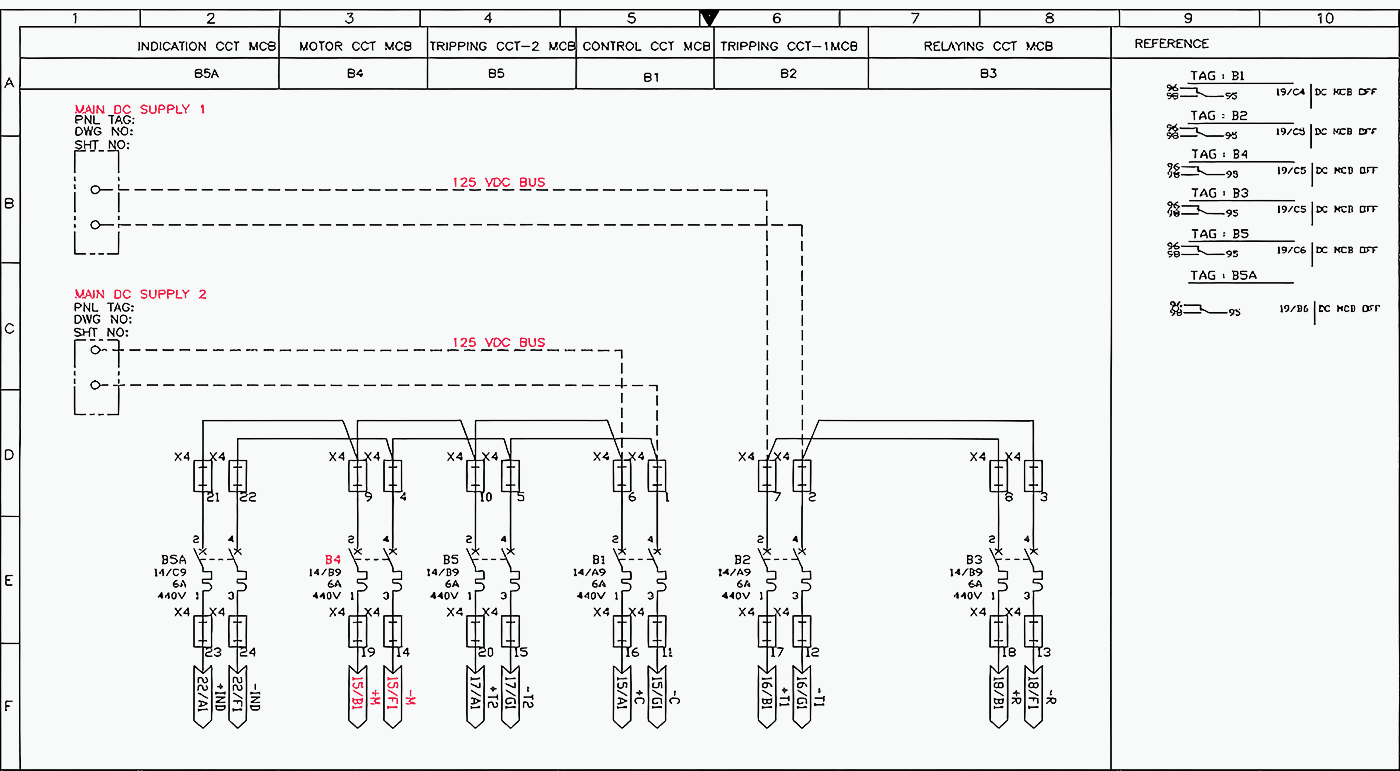
Secondly, the integrity of the Trip Circuit Supervision (TCS) relays must be verified. TCS systems are explicitly designed to continuously monitor the ohmic continuity of the trip coil and its associated external wiring, both in the closed and open positions of the circuit breaker.
However, localized high-resistance faults, such as galvanic oxidation on the terminal blocks or compromised insulation within the multi-core control cables, can severely impede adequate current flow required for tripping without necessarily triggering a low-current TCS alarm threshold.
Best practice dictates the periodic offline measurement of the trip coil resistance using a highly precise micro-ohmmeter, comparing the acquired value directly against the manufacturer’s Factory Acceptance Test (FAT) baseline documentation.
Related electrical guides & articles


Edvard Csanyi
Hi, I'm an electrical engineer, programmer and founder of EEP - Electrical Engineering Portal. I worked twelve years at Schneider Electric in the position of technical support for low- and medium-voltage projects and the design of busbar trunking systems.I'm highly specialized in the design of LV/MV switchgear and low-voltage, high-power busbar trunking (<6300A) in substations, commercial buildings and industry facilities. I'm also a professional in AutoCAD programming.
Profile: Edvard Csanyi
