
Estimated Study Time: 11 minutes
What is the biased-differential protection
The term biased-differential or percentage differential is based on the fact that the operating threshold increases with the through current. Because of that, comparison of upstream and downstream currents in the same phases is not convenient for transformer differential protection.
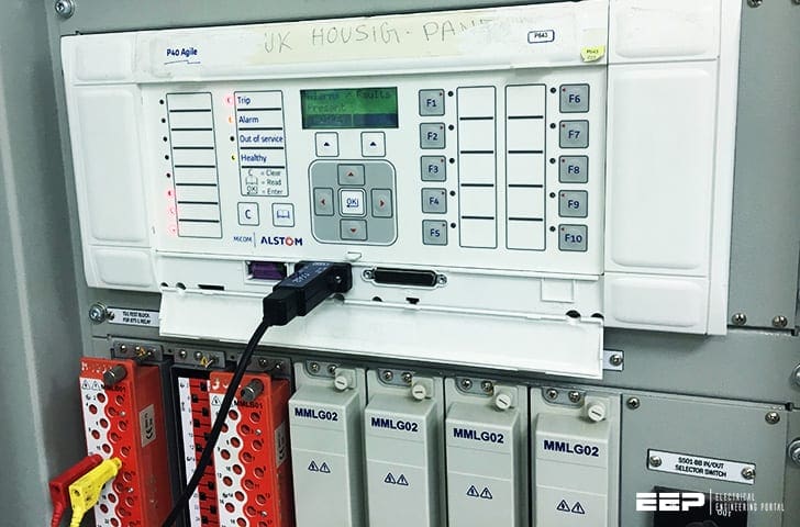 Biased-differential protection theory and application (on photo: Micom P643 Final settings test with Freja 543; full credit: Abdelrahman Fayyad via Linkedin)
Biased-differential protection is an older design of protection than high impedance circulating current. It is widely applied to two-winding transformers except those connected to the lower distribution voltages.
Until the advent of the high-impedance design, it was also applied to busbar protection, although the last few years have witnessed a new generation of biased-differential busbar protection schemes.
1. Basic principles
The basic features and principles of operation are illustrated in Figure 1. The biased-differential relay consists of two windings, an operate winding with turns No and a restraint, or bias, winding with turns NB.
The relay compares the operating force due to the out-of-balance current I1 – I2, arising from an in-zone fault with the restraint force due to the circulating current through the bias winding, arising from an external fault or load current.
For operation:
Where:
- The term I1 – I2 is known as the operating or differential current I0,
- The term (I1+I2) / 2 is known as the bias current IB
- and the term NB/No is the bias quantity B
Thus, for operation: I0 > B × IB
Modern relays embody the above principles within electronic circuitry.
Note that the above applies to relays whose characteristic is termed ‘mean bias’. An alternative approach termed ‘load bias’ analyses the relay characteristic in terms of the differential current I0 (which also flows through half of the bias winding) and a bias current IB which flows through both halves of the
bias winding.
The biased-differential relay is a low-impedance relay and compares with the high-impedance relay as follows:
- Advantages of biased scheme:
- Can operate with CTs with a lower knee point and less accuracy, since the relay is of a low-impedance type. The bias feature compensates for any CT
inaccuracy or saturated CTs; - Relay-setting calculations are less complex than with a high-impedance scheme.
- Can operate with CTs with a lower knee point and less accuracy, since the relay is of a low-impedance type. The bias feature compensates for any CT
- Disadvantages of biased scheme’.
- Not as sensitive as the high-impedance scheme (as will be shown shortly);
- The scheme circuitry is more complex than that of a high-impedance scheme.
2. Application to a two-winding transformer
Figure 3 illustrates the application of a biased-differential scheme to a two-winding transformer (to simplify the illustration only one phase is shown).
Two-winding transformers, however, produce spill currents as part of their natural operation, as follows:
2.1 Magnetizing inrush current
The phenomenon of magnetizing inrush current occurs when a transformer is energized. When the primary side of a transformer is energized from the supply system, with the secondary on open-circuit, it acts as a simple inductive reactor.
Ignoring iron losses the transformer input current is thus the magnetizing current, which is limited by the magnetizing impedance.

This current flows only in the winding connected to the source of supply, and thus causes a spill current into the biased-differential-operate winding.
Magnetising inrush has a large second-harmonic component of current and therefore, as shown in Figure 3 above, it is usual to arrange an additional bias winding, which is responsive to second-harmonic currents, to offset the effect of magnetising inrush current in the operate winding.
2.2 Transformer tap changing
Most large power transformers are equipped with tap changers. This results in the ratio of the current transformers feeding the biased-differential relay matching the ratio of the power transformer at one tap position only (usually arranged to be the nominal tap).
This occurs when the tap changer is selected to maximum (or minimum) tap, coincident with the highest out-of-zone fault current flowing through the transformer.
2.2.1 Example (132/33 kV transformer)
As an example, consider a 132/33 kV transformer with a maximum tapping of 15%. If the transformer has a percentage impedance of, say, 30% on a 100 MVA base, the HV fault current for an out-of-zone short-circuit close to the LV terminals is approximately 1450 A and, assuming an HV CT ratio of 200/1, the nominal secondary current is 7.25 A.
The corresponding LV secondary current referred to the HV side, taking into account the maximum tap position of 15%, is 6.16 A.
- Therefore, for a 1A relay, the bias current is: IB = (7.25 + 6.16) / 2 = 6.7 p.u.
- Differential current I0 = 7.25 – 6.16 = 1.1 p.u.
From Figure 2, a percentage bias of 20% would ensure stability for this condition.
3. Practical application
Figure 4 illustrates a practical application of a biased-differential protection to a 132/33 kV transformer.
The key points of this application are:
Point #1
The biased-differential scheme functions in conjunction with HV and LV restricted-earth-fault schemes.
Point #2
The secondary wiring is arranged to mimic the primary connections. Thus a through current in the primary results in a corresponding balance of current in the secondary, with no spill current in the operate winding (apart from any due to the tap changer being off nominal tap).
Point #3
The star-delta-star interposing-transformer arrangement may seem somewhat puzzling. Since earth-fault zero-sequence current cannot pass from the 33 kV to the 132 kV side of the transformer (i.e. it cannot flow through a delta-star winding), it must be filtered out of the interposing transformer secondary winding.
The star-delta-star transformer achieves this.
The zero-sequence current is unable to flow in the unearthed star winding 1S1, 1S2 and thus, to obtain current (flux) balance across the transformer, it circulates around the delta winding 2S1, 2S2.
Point #4
The zig-zag, or interconnected-star, earthing transformer is the usual system for earthing the 33 kV network.
It presents a high impedance to balanced three-phase (positive-phase-sequence) voltages, but a low impedance to in-phase (zero-sequence) voltages. This is because the windings produce opposing fluxes in each core, under zero-sequence conditions.

Point #5
Figure 4 shows how current balance is achieved for an out-of-zone earth fault and Figure 5 illustrates the corresponding phase-sequence network.
Furthermore, there would be virtually no current flow through the star-delta-star interposing transformer. This therefore causes the currents flowing out of the star-delta interposing transformer to flow into the biased-differential-relay operate winding.
It is worth recognizing that the biased-differential relay is connected so that it will only respond to positive- and negative-sequence currents (because there is no zero-sequence return path from the relay star point).
Transformer biased differential protection (VIDEO)
This video shows the philosophy behind biased transformer differential protection
Sources //
- Power System Commissioning and Maintenance Practice-Institution of Engineering and Technology by Harker, Keith (Purchase hardcopy from Amazon)
- Current transformers: how to specify them by P. Fonti (Schneider Electric)
Related electrical guides & articles


Edvard Csanyi
Hi, I'm an electrical engineer, programmer and founder of EEP - Electrical Engineering Portal. I worked twelve years at Schneider Electric in the position of technical support for low- and medium-voltage projects and the design of busbar trunking systems.I'm highly specialized in the design of LV/MV switchgear and low-voltage, high-power busbar trunking (<6300A) in substations, commercial buildings and industry facilities. I'm also a professional in AutoCAD programming.
Profile: Edvard Csanyi

Nice and sufficient information.
Please am into electrical jobs if there’s any maintenance electrical jobs please am interested please thanks
A very good interactive explanation of bias differential protection
Article presentation is easy to follow. Highly educative.
Well explained article about differential relay.
you are awesome man. I have been looking for this theory so long. Can you please make another webpage regarding differential and ref protection along with stabilizing resister, please.
Dear sir,
Very good article on the differential protection
How to calculate fault current of substation and design relay coordination
I want to know how to use a high pot AC tester