
Estimated Study Time: 34 minutes
Substation Schematics Have Changed
Substation schematics have changed, a lot. Modern digital substations now include schematics that never existed in old substations. Actually, it’s a totally different philosophy and this is not easy for “old engineers” to adopt and switch to new logic and new substation schematics. Analyzing schematics for high-voltage (HV) substations is an unforgiving discipline.
 Biggest Mistakes in Analyzing Modern Substation Schematics
A single misinterpreted line, an overlooked logical node, or a misunderstood protection zone can lead to catastrophic equipment failure, grid instability, or severe safety hazards. As the industry transitions from conventional hardwired systems to highly integrated digital architectures, the complexity of these schematics has increased exponentially.
Engineers are no longer just tracing copper; they are decoding complex network topologies, logical bindings, and synchronized data streams.
Whether you are dealing with legacy electromechanical relays or modern Intelligent Electronic Devices (IEDs) operating on a process bus, the potential for error is vast.
The following breakdown details the fifteen most significant mistakes made when analyzing high-voltage substation schematics, examining both the physical and digital domains.
Ok, let’s dive into the article. Buckle up and pour yourself a large coffee!
- Misinterpreting Protection Zones and Overlapping
- Confusing Physical Connections with Logical Nodes in IEC 61850
- Ignoring the Nuances of the Substation Configuration Language (SCL):
- Overlooking DC Control Circuit Transients and Voltage Drops:
- Misunderstanding Grounding and Bonding Paths
- Failure to Correlate Three-Line Diagrams with Single-Line Diagrams
- Incorrect Integration of Generator Circuit Breakers (GCB)
- Neglecting Interlocking Logic in Hybrid Switchgear
- Misjudging CT/VT Polarities and Burden Constraints
- Underestimating Cyber-Physical Attack Vectors in Schematic Topology
- Poor Translation of Legacy Schematics to Modern IED Logic
- Disregarding Merging Unit (MU) Synchronization in Process Bus Architecture
- Inadequate Review of Breaker Failure (BF) Scheme Routing
- Overlooking Arc Flash Mitigation Control Loops
- Failing to Update As-Built Drawings After Asset Management Interventions
- Conclusion & What to Do
- Attachment (PDF) 🔗 Download ‘Digital Power Substation Communications Over Time-Sensitive Networks’
1. Misinterpreting Protection Zones and Overlapping
One of the most foundational errors in schematic analysis is failing to accurately define and overlap protection zones. Protection zones are defined by the location of Current Transformers (CTs).
A common mistake is analyzing the Single-Line Diagram (SLD) without verifying the physical placement of the CTs relative to the circuit breakers.
Schematics must be scrutinized to ensure that every piece of primary equipment is covered by at least two independent overlapping zones.
Take an example depicted in Figure 1.
Figure 1 – Substation schematic error: Incorrect protection zone overlapping
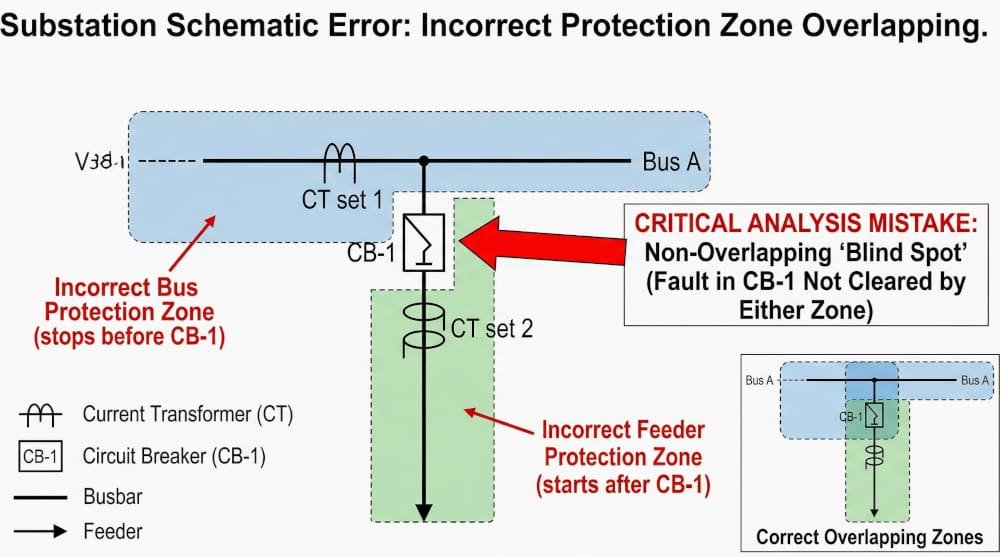
This single-line diagram (Figure 1) illustrates the specific error, following the description below:
The Error (Main Diagram): The analysis incorrectly places the boundary of the blue zone before the breaker and the green zone after the breaker, creating a clear white gap (blind spot) directly over the equipment. A red arrow highlights that a fault occurring within that gap would not be cleared by either protection scheme.
The Correct Design (Inset): The small inset diagram in the bottom right shows how the zones must overlap, ensuring the circuit breaker is covered by both schemes and eliminating any blind spot.
Correctly analyzing these boundary conditions is vital for preventing unprotected equipment from causing catastrophic substation failure.
2. Confusing Physical Connections with Logical Nodes in IEC 61850
In digital substations utilizing the IEC 61850 standard, the paradigm shifts entirely. A critical mistake is treating the schematic as a purely physical representation. Engineers accustomed to conventional substations often look for hardwired trip signals. In a digital environment, the physical drawing might only show an Ethernet connection between an IED and a switch.
The actual “wiring” exists in the logical realm via GOOSE (Generic Object Oriented Substation Event) messages.
Failing to cross-reference the physical Ethernet topology with the logical node mapping (e.g., PTRC for protection trip conditioning, XCBR for circuit breaker modeling) leads to a complete misunderstanding of how a trip signal propagates from the protection relay to the breaker.
Figure 2 – Distance protection zones with marked PTRC and XCBR logical nodes
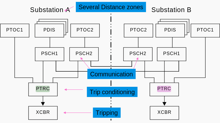
In a conventional substation, a wire is a physical reality—if you see a copper cable running from a protection relay to a breaker’s trip coil, that is the path the signal takes. In a digital substation following IEC 61850, this intuition becomes a liability.
The actual “connection” is a Logical Node mapping defined in the software (SCL files). A GOOSE (Generic Object Oriented Substation Event) message might be published by a protection IED and subscribed to by five different breaker IEDs. Physically, they all connect to the same switch, but logically, they are separate point-to-point or point-to-multipoint “virtual wires.”
Analyzing the physical layout without the logical mapping is like looking at a highway and trying to guess which specific car is carrying a specific letter; the infrastructure is visible, but the intent is hidden in the data packets.
The following diagrams visualizes this disconnect. Figure 3 depicts the Physical View (what you see in the yard) and Figure 4 depicts the Logical View (the functional protection logic) to see how a single physical cable supports multiple virtual connections.
Figure 3 – Physical View: Visualizing the ‘SCD’ (Substation Configuration Description) physical layout. Fiber cables connect IEDs to the Process Bus switch
Figure 4 – Logical View: Visualizing ‘GOOSE’ and ‘SV’ (Sampled Values) data flows. These virtual wires define peer-to-peer behavior between Logical Nodes
3. Ignoring the Nuances of the Substation Configuration Language (SCL)
Tied directly to the previous point is the mistake of analyzing the drawn schematic without validating it against the Substation Configuration Language (SCL) files. The paper schematic is often just a high-level overview; the true operational schematic is the System Configuration Description (SCD) file.
Engineers sometimes fail to verify that the dataset configurations, report control blocks, and GOOSE control blocks defined in the SCD file match the intended logic shown on the engineering drawings.
If an IED’s capability description (ICD) is updated or altered without reflecting those changes in the overarching SCD file, the physical schematic becomes dangerously obsolete, and the system may fail to operate during a fault.
Here are the primary reasons why engineers sometimes miss these critical verifications:
3.1 The “Invisible Wiring” Problem
In traditional substations, a physical copper wire connected a relay to a breaker. If the drawing showed a wire, you could physically look at the panel and trace it. In an IEC 61850 digital substation, that physical wire is replaced by a fiber optic cable carrying thousands of signals.
The “wiring” is now defined in software (specifically in System Configuration Description or SCD files). Traditional 2D CAD drawings are excellent for showing physical connections but are very poor tools for representing complex, multi-layered digital data models.
3.2 Disconnect Between Tools and Teams
Substation design often involves a split workflow:
- CAD Drafters: Create the physical layouts and elementary diagrams.
- Protection & Control (P&C) Engineers: Calculate the protection logic.
- Automation/SCADA Engineers: Build the IEC 61850 data models and SCL (Substation Configuration Language) files.
Because the tools to generate the physical drawings (like AutoCAD) and the tools to configure the digital logic (like vendor-specific IED configurators) are rarely integrated seamlessly, manual transcription is required.
Discrepancies easily creep in during this handoff, and because the teams are siloed, verification steps are often assumed to be handled by “the other guy.”
Watch Video – IEC61850 SCL Engineering – Building a Substation Configuration SCD
3.3 The Sheer Scale and Complexity of the Data Model
A single Intelligent Electronic Device (IED), like a modern protection relay, can contain hundreds or thousands of data objects.
- Datasets: Engineers must group the right data objects together.
- RCBs (Report Control Blocks): They must define how and when that dataset is sent to the HMI (e.g., buffered or unbuffered, trigger options).
- GOOSE Control Blocks: They must define the high-speed, peer-to-peer multicast parameters (MAC addresses, VLAN IDs, AppIDs).
Verifying every single parameter manually on a spreadsheet or PDF report against the actual database is incredibly tedious, leading to “default acceptance”—engineers simply trusting the vendor’s auto-generated defaults rather than verifying each specific project requirement.
3.4 Late-Stage Commissioning Pressure
Digital configuration issues often don’t become apparent until the FAT (Factory Acceptance Test) or SAT (Site Acceptance Test) phases. When a GOOSE message fails to trip a breaker during testing, engineers are usually under immense schedule pressure to fix the issue on the fly.
They might make a quick patch in the software to make the test pass, but fail to back-annotate those changes into the official design drawings, leaving the documentation permanently out of sync with reality.
Related electrical guides & articles


Edvard Csanyi
Hi, I'm an electrical engineer, programmer and founder of EEP - Electrical Engineering Portal. I worked twelve years at Schneider Electric in the position of technical support for low- and medium-voltage projects and the design of busbar trunking systems.I'm highly specialized in the design of LV/MV switchgear and low-voltage, high-power busbar trunking (<6300A) in substations, commercial buildings and industry facilities. I'm also a professional in AutoCAD programming.
Profile: Edvard Csanyi
