
Estimated Study Time: 55 minutes
Decoding 24kV Switchgear Schematics
This comprehensive guide serves as your master blueprint for decoding 24kV switchgear schematics. While the primary focus of this guide is the secondary wiring and automation schematics, we will break down the system layer by layer, starting with the System Specifications and Single Line Diagram (SLD), followed by equipment such as CBs, CTs/VTs, and finally strict LSC2B compartmentalization. For your reference, the complete 101-page PDF of the switchgear drawings is included.
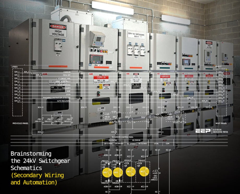 Brainstorming the 24kV Switchgear Schematics (Secondary Wiring and Automation)
Beyond the primary hardware, the true complexity of a substation lies in its secondary wiring and automation. This article provides an extensive deep-dive into the critical hardwired circuits that dictate operational safety and grid stability.
We will trace the exact logic paths of the Closing and Tripping Circuits, explore how Binary Inputs bridge the gap between mechanical switches and digital relays, and map out the distributed architecture of Alarm Gathering and emergency Load Shedding.
Through a forensic examination of these schematics, one can understand the intricate balance between high-capacity power handling, rigorous safety interlocking, and advanced digital protection schemes.
Ready for a deep dive? Grab a coffee, settle in, and let’s get started.
- System Specifications and Operating Parameters
- Single Line Diagram (SLD) and Substation Topology
- Instrument Transformers (CTs and VTs)
- Vacuum Circuit Breakers (VD4) and Interruption Technology
- Physical Compartmentalization and Operational Safety
- Protection, Control, and Digital Automation (IEC 61850)
- Low Voltage (LVD) Compartment and Metering
- Important Switchgear Circuits Represented in Schematics:
- Conclusion
- ATTACHMENT (PDF) 🔗 Download “Complete 24kV Switchgear Schematics (PDF, 101 pages; 2.9Mb)”
1. System Specifications and Operating Parameters
At the core of the Switchgear design are the strict electrical ratings required to handle both continuous generation loads and severe fault conditions. The UniGear ZS1 switchgear is configured for a 22kV, 3-phase, 3-wire, 50Hz system, with a maximum rated voltage of 24kV.
Insulation coordination is a critical factor in power systems, which are often exposed to severe atmospheric overvoltages. The switchgear boasts a rated power-frequency withstand voltage of 50kV and a lightning impulse withstand voltage (BIL) of 125kV.
Thermal and electro-dynamic limits are equally stringent. The main copper busbar is rated for a continuous current of 2000A, constructed from 2 × 80 x 10mm² insulated copper bars.
Under fault conditions, the switchgear is engineered to endure a rated short-time withstand current of 25kA for 1 second, and a dynamic peak withstand current of 63kA.
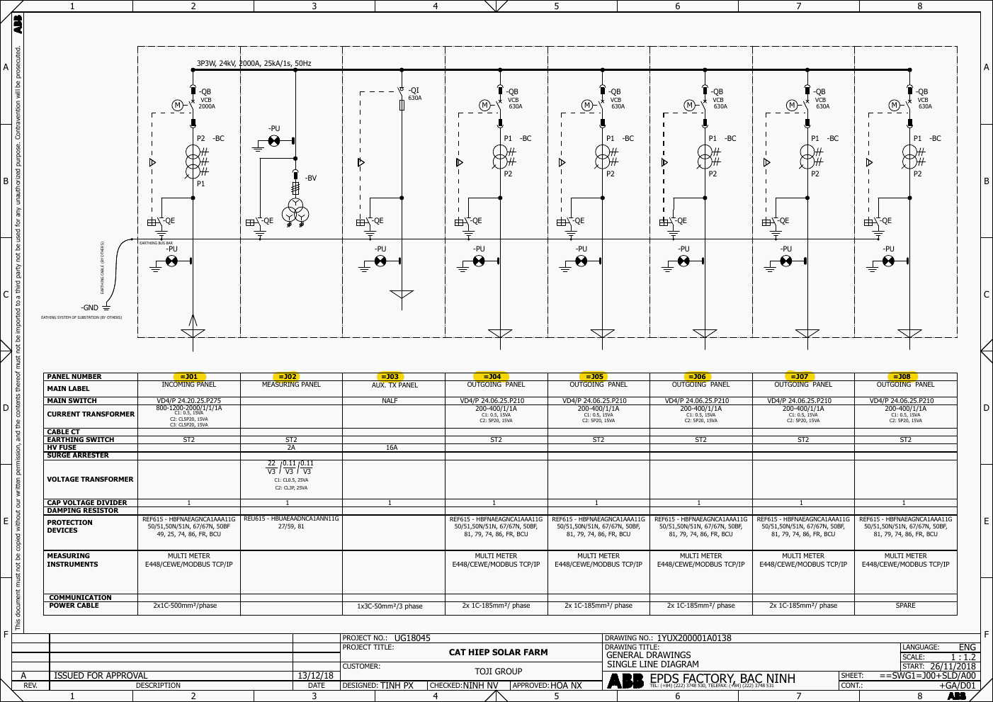
Figure 1 – Single-line diagram of a 24kV switchgear (click to zoom)
The ability to withstand 63kA peak without structural deformation speaks to the mechanical bracing of the busbar supports, which must counteract immense electromagnetic forces during asymmetrical short-circuit events.
The enclosure offers an ingress protection rating of IP4X externally, preventing the entry of wires or objects larger than 1mm, and IP20 internally, ensuring personnel safety against accidental contact with live parts during compartment access.
In order to effectively continue to follow the discussion, I advise you to download a complete set of UniGear ZS1 panel drawings (101 pages, PDF), which includes the following:
- Single-line diagram
- Front and sectional views of switchgear panels
- Wiring and control schematics
- Protection and relay configurations
- Layout and assembly diagrams
2. Single Line Diagram (SLD) and Substation Topology
The Single Line Diagram (SLD) provides the functional topology of the 8-panel switchgear lineup, designated as SWG1 (Panels J01 through J08).
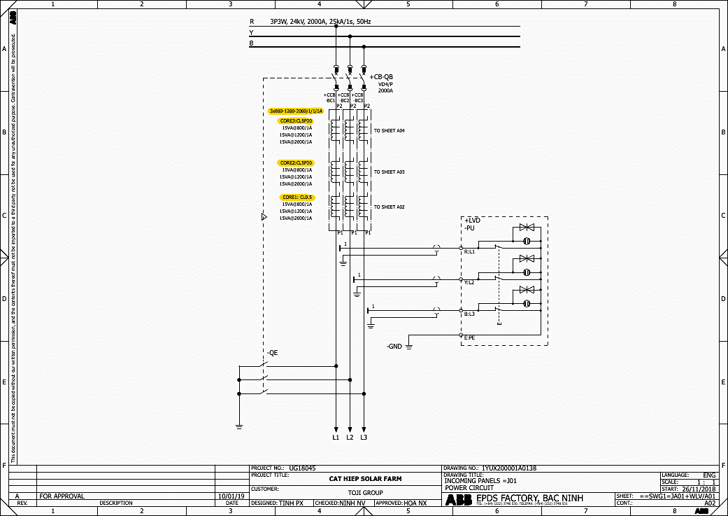
2.1 Incoming Panel =J01
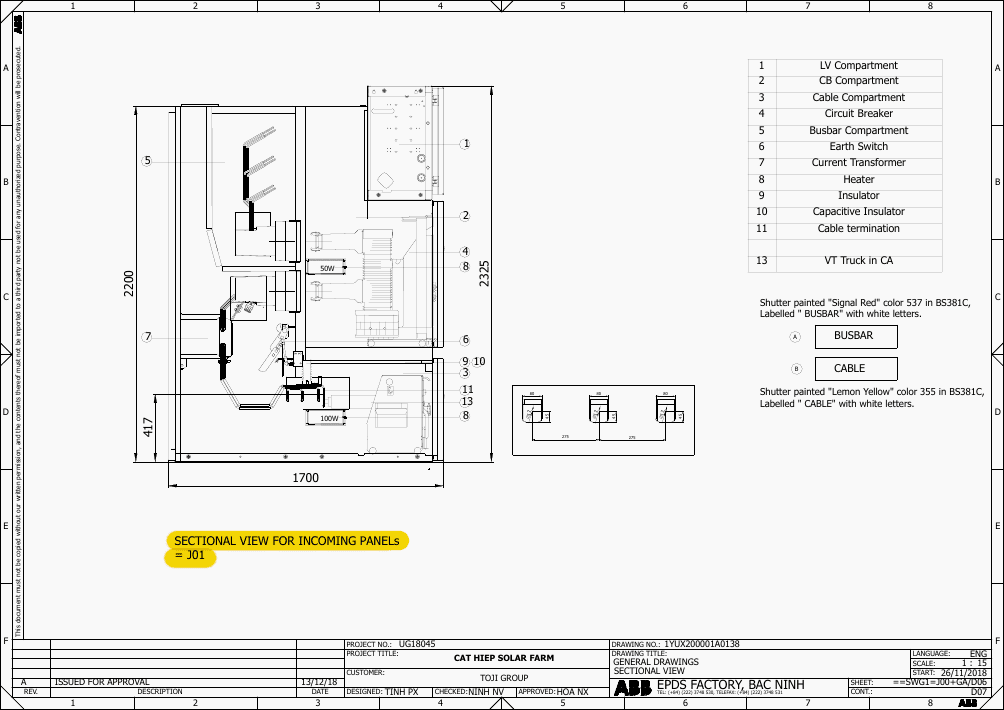
It serves as the primary electrical gateway for the entire 24kV switchgear substation. It is equipped with a heavy-duty 2000A VD4 Vacuum Circuit Breaker (VCB). It handles the maximum continuous current (up to 2000A) entering the substation and transfers it safely to the main horizontal busbars, which then distribute the power to the rest of the panels (like the VT and Outgoing panels).
It houses high-capacity Current Transformers (up to 2000/1A) and a dedicated REF615 protection relay.
Figure 2 – Sectional view of Incoming Panel =J01 (click to zoom)
2.2 Metering (Measuring) Panel =J02
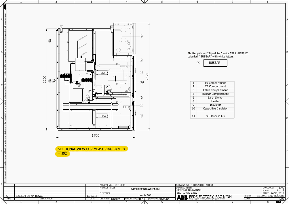
Its primary role is to serve as the substation’s “eyes” for voltage. It houses the primary Voltage Transformers (VTs). These VTs step the dangerous 22kV busbar voltage down to a safe, low voltage (110V) that instruments can read. The panel utilizes an ABB REU615 relay dedicated to voltage-based protection.
It monitors for overvoltage, undervoltage, and frequency anomalies.
It provides the critical busbar voltage reference signal to the Incoming Panel (J01) so the main breaker can verify it is perfectly synchronized with the utility grid before closing.
Figure 3 – Sectional view of Metering Panel =J02 (click to zoom)
2.3 Auxiliary Transformer Panel (=J03)
Instead of a VCB, this panel utilizes a NALF 630A Load Break Switch (LBS) combined with 16A high-voltage fuses. This is a highly effective, economical design for feeding the station’s internal auxiliary power transformer.
The fuses provide rapid clearing of internal transformer faults, while the LBS allows for safe, off-load or light-load isolation.
Figure 4 – Sectional view of Auxiliary transformer panel =J03 (click to zoom)
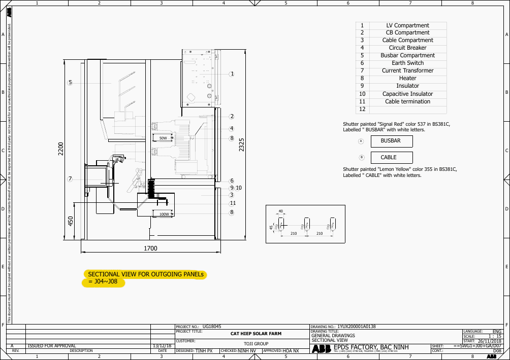
2.4 Outgoing Panels (=J04 to =J08)
These five panels distribute power to the various circuits of the power system. Each is equipped with a 630A-rated VD4/P Vacuum Circuit Breaker and is configured to accept 2x 1C-185mm2 per phase power cables via bottom entry.
Figure 5 – Sectional view of Outgoing Panels =J04 to =J08 (click to zoom)
3. Instrument Transformers (CTs and VTs)
Accurate power measurement and reliable fault detection depend entirely on the performance of the instrument transformers. The schematics specify wound-type Current Transformers (LZZBJ9-24/178h/4) and removable Voltage Transformers (JDZXR26-20).
The CTs in the incoming and outgoing panels feature a multi-ratio primary winding (800-1200-2000/1/1/1A for the incoming, and 200-400/1/1A for the outgoing). This allows the power system operators to adjust the CT ratio as the facility’s generation capacity scales.
Figure 6 – CTs 3×800-1200-2000/1/1/1A (click to zoom)
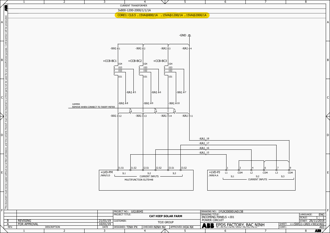
The CTs possess three distinct secondary cores:
Core 1 (Metering): Rated at Class 0.5 with a 15VA burden. This high accuracy ensures that the revenue and operational metering data is precise under normal load conditions.
Figure 7 – CTs CORE1: CL0.5, 15VA@800/1A, 15VA@1200/1A, 15VA@2000/1A (click to zoom)
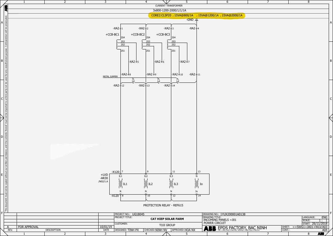
Cores 2 & 3 (Protection): Rated at Class 5P20 with a 15VA burden. The 5P20 designation guarantees that the composite error will not exceed 5% even when the primary current reaches 20 times the nominal rating.
This prevents CT core saturation during severe overcurrent events, allowing the protection relays to accurately read the fault magnitude and execute the correct trip logic.
Figure 8 – CTs CORE2:CL5P20, 15VA@800/1A, 15VA@1200/1A, 15VA@2000/1A (click to zoom)
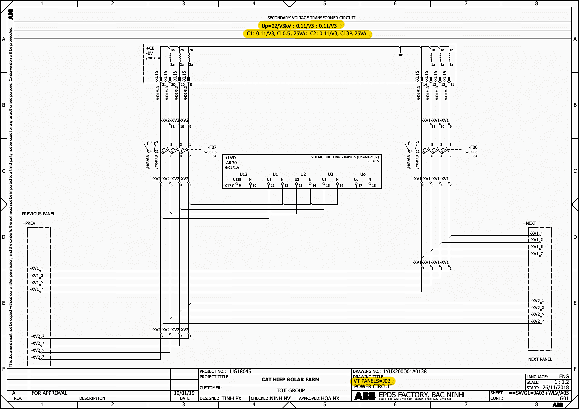
The VTs in the measuring panel provide a ratio of 22/√3 kV to 0.11/√3 kV. They feature a Class 0.5 core (25VA) for high-accuracy voltage measurement and a Class 3P core (25VA) for voltage-based protection elements (such as undervoltage, overvoltage, and residual overvoltage).
Furthermore, capacitive voltage dividers (CGR 24kV) are installed across the panels to interface with DXN-Q-1 LED voltage indicators, providing operators with immediate visual confirmation of line voltage presence.
Figure 9 – Secondary voltage transformer circuit (click to zoom)
4. Vacuum Circuit Breakers (VD4) and Interruption Technology
The primary switching devices specified in this ABB switchgear are the VD4/P series Vacuum Circuit Breakers. The incoming panel utilizes a 2000A variant, while the outgoing panels use 630A variants.
Vacuum interruption technology is highly favored in power and industrial applications due to its maintenance-free arcing chamber and exceptionally rapid dielectric recovery. When the VD4 contacts separate during a fault, the metallic vapor arc is extinguished at the first current zero-crossing.
The vacuum environment rapidly recovers its dielectric strength, preventing arc restrike even under the high rate-of-rise of recovery voltage (RRRV) typical in highly inductive or capacitive circuits.
This capability is crucial for clearing transient faults (like lightning flashovers) without causing sustained outages to the power system generation export.
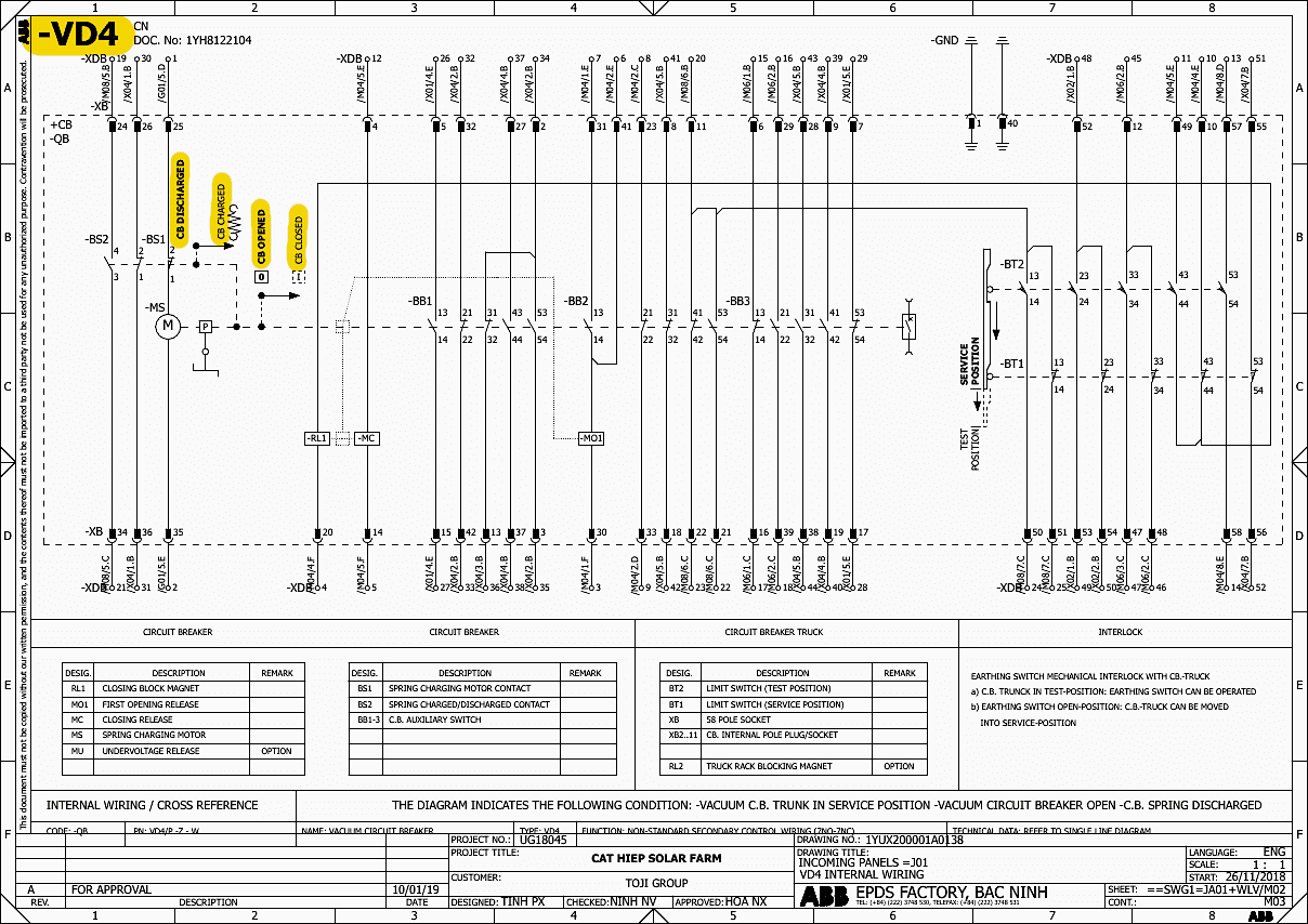
Figure 9 -Schematic of a Vacuum Circuit Breaker (VD4) (click to zoom)
5. Physical Compartmentalization and Operational Safety
In energized high-voltage environments, operational safety and technical diagnostics are paramount. The UniGear ZS1 achieves this through strict LSC2B (Loss of Service Continuity Category 2B) compartmentalization. The physical cross-sections (Drawings D06 through D09) reveal four completely segregated, earthed metal compartments:
- Low Voltage (LV) Control Compartment.
- Circuit Breaker (CB) Compartment.
- Main Busbar Compartment.
- Power Cable Compartment.
This segregation allows maintenance personnel to safely access the cable or breaker compartments while the main busbar remains energized. If an internal arc fault occurs within one compartment, the metallic partitions prevent the plasma and thermal blast from propagating to adjacent sections.
Related electrical guides & articles


Edvard Csanyi
Hi, I'm an electrical engineer, programmer and founder of EEP - Electrical Engineering Portal. I worked twelve years at Schneider Electric in the position of technical support for low- and medium-voltage projects and the design of busbar trunking systems.I'm highly specialized in the design of LV/MV switchgear and low-voltage, high-power busbar trunking (<6300A) in substations, commercial buildings and industry facilities. I'm also a professional in AutoCAD programming.
Profile: Edvard Csanyi
