Protection and control schemes design
Modern numerical distance relays are equipped with a wide range of protection features, including overcurrent, overvoltage, undervoltage, underfrequency, overfrequency, breaker failure, synchronism check, power swing blocking and tripping, pilot protection schemes, digital relay-to-relay communications capability, logic programmability, and sophisticated math functionality.
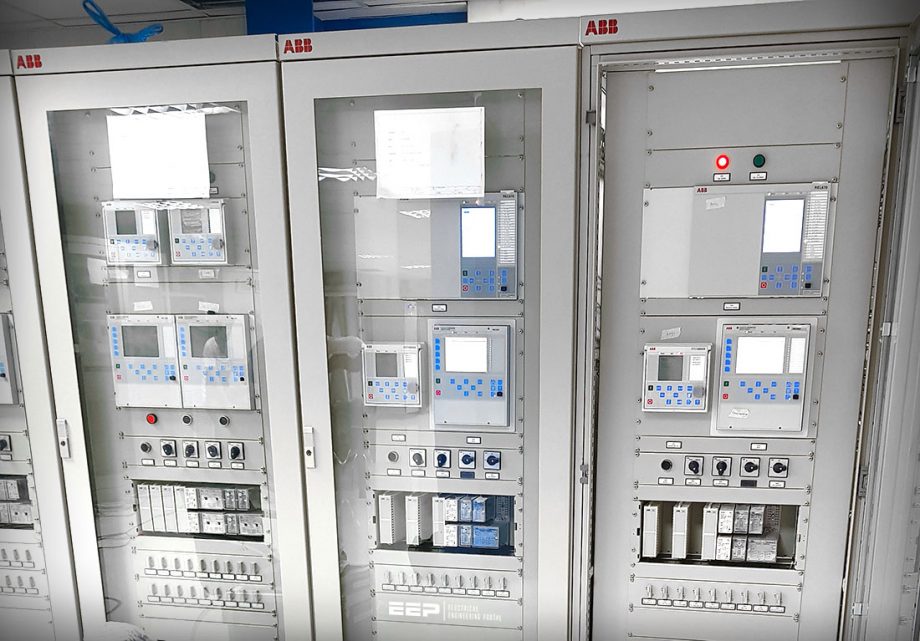
Protection engineers now have the tools and flexibility to design more secure and dependable protection and control schemes, which will increase the security and reliability of electric power systems. Functional integration is a feature found in modern numerical distance-type relays.
The increased number of relay settings, functionality, design flexibility, and programmability in modern distance relays has also introduced a higher level of complexity for the user and an increased risk of making application and settings errors.
Proper operator training and appropriate testing of the designed schemes helps in taking full advantage of functional integration offered by modern distance relays and reduces any potential risks of misapplications.
Multifunctional distance relays are now used in new or upgraded integrated substation protection, monitoring, and control systems and are becoming the main data sources for measurements needed by the local substation HMI or SCADA master.
In this section, we provide several examples of breaker failure protection applications to illustrate the use and the benefits of functional integration in modern numerical distance relays.
- How Numerical Distance Relays Improves System Reliability
- Breaker Failure Protection Applications
- Application of Integrated Sensitive Negative- and Zero-Sequence Overcurrent Functions in Distance Protection
- Numerical Distance Relay Settings Group Change
- Application of Directional Ground Current Elements (67N) and Directional Negative-Sequence Current Elements (67Q) With Distance Protection
- Single-Phase Tripping and Reclosing
- Three-Terminal Line Protection Application
- Relay-to-Relay Communications Application
1. How numerical distance relays improves system reliability
Protection engineers strive to achieve high-speed tripping for all transmission line faults through the use of communications-assisted protective relaying.
In traditional pilot relaying schemes, the relay systems send and receive logic-based information between line terminals to determine whether the fault is internal or external to the protected line section. Traditional pilot relaying schemes require costly external communications equipment.
Later, we’ll discuss applications of relay-to-relay digital communications in single-phase tripping and reclosing applications to aid the phase selection function of distance-type relays and avoid three-phase tripping during simultaneous single-phase-to-ground faults near one terminal of a double-circuit transmission line.
In three-terminal line protection applications where high-speed tripping is essential, loss of a communications channel between any two of the three terminals renders the high-speed pilot protection scheme inoperable. Relay-to-relay communications and relay programmable logic can maintain high-speed protection even in the event of the loss of one channel between any two of the three terminals.
Suggested Course – Distance Protection Course: Learn How Distance Relay Protects Line and How to Set It Correctly
Distance Protection Course: Learn How Distance Relay Protects Line and How to Set It Correctly
Go back to the Contents Table ↑
2. Breaker Failure Protection Applications
2.1 Communication in Conventional Breaker Failure Protection
Communication is used for breaker failure protection in conventional systems in the case of a bus fault when one of the transmission line breakers fails to trip. The fault can be cleared using remote-end backup protection (Zone 2 trip).
However, if high-speed fault clearing is required for dynamic stability or power quality reasons, the breaker failure protection will send a direct or permissive intertrip signal to the remote end using a dedicated signaling device or use the available binary signals in the data message of a multifunctional line protection IED.
When the signal is received, the IED will trip the local line breaker (or breakers in the case of a breaker-and-a-half or ring-bus) to clear the fault, thus achieving faster fault clearing compared to a Zone 2 or time-overcurrent remote backup trip.
Figure 1 – Breaker failure protection


Go back to the Contents Table ↑
2.2 Distributed Breaker Failure Protection Application
Figure 2 shows an example of a distributed breaker failure protection scheme. When the relay detects a fault condition on the protected line, it issues a trip signal in order to clear the fault. This can be a GOOSE message with the trip bit pair indicating the operation of the trip output function of the IED.
The bay controller that implements the distributed breaker failure function subscribes to this message, and, as soon as the GOOSE message is received, the bay controller starts the breaker failure timer.
If the breaker fails to trip, the breaker failure relay (BFR) indicates a breaker failure and sends a GOOSE message to the substation LAN to trip adjacent breakers in order to clear the fault.
Figure 2 – Distributed breaker failure protection
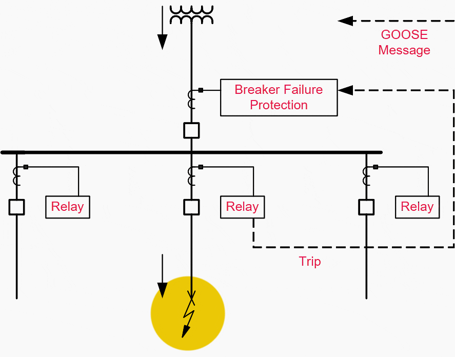

In some cases, the BFR function in the bay controller can also send a trip GOOSE message to the network that will attempt to retrip the faulted line breaker through a different physical connection or another breaker IED connected to the substation LAN.
When the breaker failure protection function is built into the distance relay that detects the fault condition, it detects a failure of the breaker and issues a GOOSE message with a bit pair set to indicate the breaker failure condition.
Distributed communications-based breaker failure protection can be designed in two different ways:
- As a function in an IED that initiates the breaker failure protection when it sees the trip signal from the relay protecting the faulted power system device.
- As a built-in function in the protection IED that detects the fault and issues the trip signal.
The breaker failure protection (BFP) element can be configured to operate for trips triggered by protection elements within the relay or via an external protection trip. The latter is achieved by allocating one of the relay optoisolated inputs or virtual inputs to “external trip”.
Go back to the Contents Table ↑
3. Application of Integrated Sensitive Negative- and Zero-Sequence Overcurrent Functions in Distance Protection
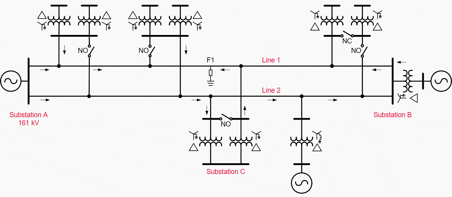
In Figure 3, Line 1 in Substation A is protected with an electromechanical distance relay scheme in a permissive underreach mode and with discrete phase and ground electromechanical directional overcurrent relays for backup protection. For the same line in Substations B and C, static type distance relays are used in a permissive underreaching mode and directional ground overcurrent relays are provided for the backup protection function.
According to the topology of the network shown in Figure 3 and the short-circuit current contributions at the faulted locations, the quadrilateral distance relay at Substation C may not be able to detect a resistive ground fault (30 ohms) at Location F1.
This is due to the limited resistive reach of the distance relay and the load impedance of the system. In this case, only the time-delayed ground directional protection is able to detect and trip the circuit breaker of the faulted line at Substation C.
Note that the directional ground overcurrent relays may be impacted at all tapped substations if not set long enough to override the longest fault clearing time of the distance devices at Substations A and B.
Figure 3 – Power system single-line diagram (click to zoom)

In order to improve the reliability and the security of the discussed power network, modern numerical distance multifunctional relays can be employed. A definite improvement in protection performance is achieved by enabling sensitive directional negative- and zero-sequence current elements in conjunction with the flexible distance protection application provided in the same device.
The desired high-speed operation of the line protection by means of relay-to-relay communications and programmable logic is assured even in the event of one-channel loss between any two terminals.
Finally, adaptive techniques can be considered as an alternative solution by changing relay settings groups according to the prevailing system and load conditions. The approach to adapt new resistive reach settings is possible in today’s modern distance protection devices.
Suggested Reading – 13 terms concerning relaying, measurements, and breakers used by protection engineers
13 terms concerning relaying, measurements, and breakers used by protection engineers
Go back to the Contents Table ↑
4. Numerical Distance Relay Settings Group Change
Protection engineers can use innovative and creative applications in both protection and control areas due to the flexibility of multiple inputs and outputs provided in numerical relays.
The use of multifunctional distance relays with relay-to-relay communications offers numerous opportunities to enhance control functions and, at the same time, automatically improve the protection performance through a change of settings groups to accommodate the change in network configurations.
Figure 4 – Relay settings group change
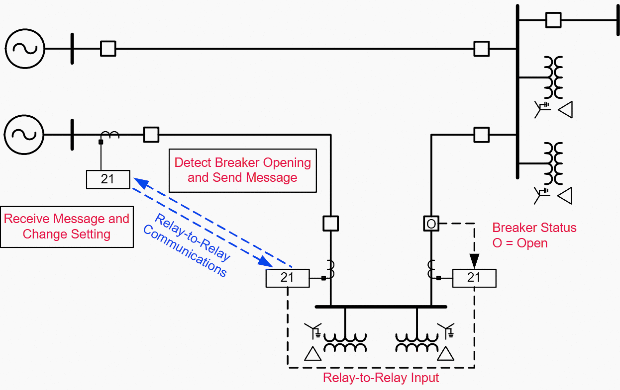

In Figure 4, if the circuit breaker is taken out from service for maintenance reasons, then it is possible to automatically change the remote line end protection settings using relay-to-relay communications. The protection is enhanced without any human intervention.
Change of settings groups is possible for various conditions listed below:
- Change the integrated protection functions and settings based on load and breaker status in order to enhance sensitivity and to improve protection coordination.
- Change in relay settings based on source conditions that affect sequence current and/or voltage contributions to the fault location.
- Change in remote distance protection settings based on system configuration.
- Change in settings for adaptive circuit breaker reclosing schemes.
- Condition the remote line end circuit breaker reclosing.
Go back to the Contents Table ↑
5. Application of Directional Ground Current Elements (67N) and Directional Negative-Sequence Current Elements (67Q) With Distance Protection
Conventional distance relays can be ineffective in some cases due to strong zero-sequence current infeed from tapped loads. Depending on the network topology, phase-to-ground faults in some locations on the line may remain undetected for a long time until tripping of the breakers takes place at the tapped station as illustrated in the figures below.
A phase-to-ground fault near the strong terminal source in Figure 5 can make the distance relays at the weak terminal end ineffective due to the relatively low zero-sequence current contribution to the fault.
Figure 5 – Power system single-line diagram
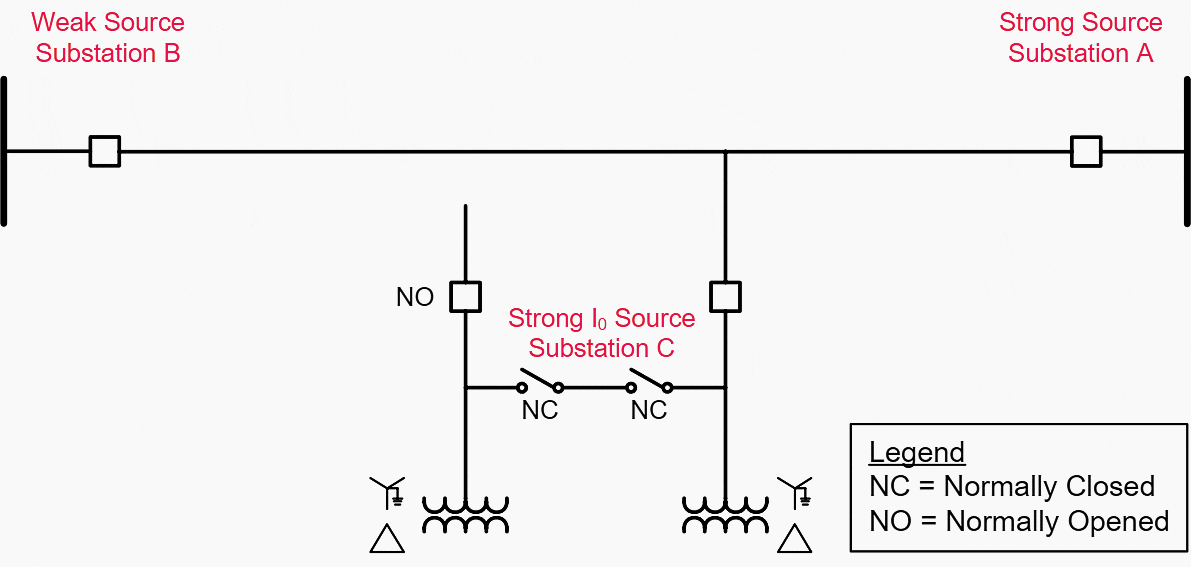

In this case, tripping the line circuit breakers at the strong source terminal does not considerably increase the zero-sequence current contribution from the weak source until the tapped load at Substation C is tripped from the line. Tripping the load at Substation C is undesirable because this affects the customers and prevents the normal circuit breaker permutation on the healthy line.
Note that sufficient negative-sequence current is available at the weak terminal source and could be used to supervise the distance elements in order to achieve selective tripping before the removal of the tapped load at Substation C.
Figures 6a, 6b, and 6c indicate the fault points and the fault current contributions for the system shown in Figure 5.
Figure 6a – Fault current contributions for a fault at Substation A – Note status of breakers at Substations A and C


Figure 6b – Fault current contributions for a fault at Substation A – Note status of breakers at Substations A and C
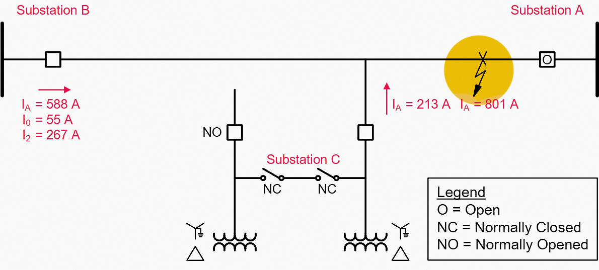

Figure 6c – Fault current contributions for a fault at Substation A – Note status of breakers at Substations A and C
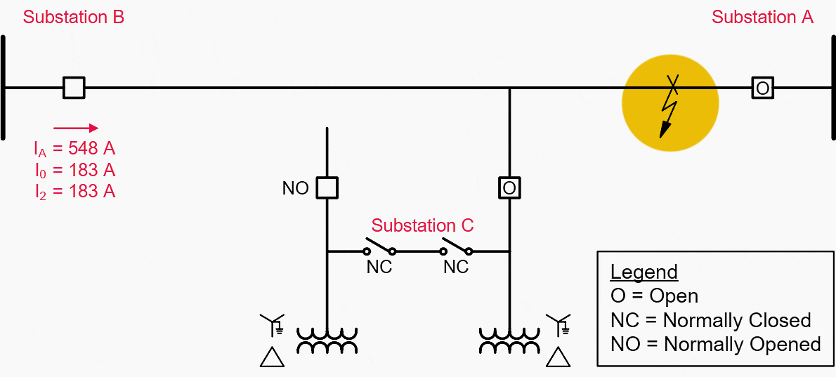

For phase-to-ground faults near the weak terminal source, as illustrated in Figure 7 below, very little zero-sequence current contribution is available at the strong terminal source, which makes the distance relays unable to operate at that end.
If sensitive distance protection is employed at the strong terminal source, sequential tripping will result once the weak source terminal is opened. Integrated very sensitive directional ground current element (67N) and directional negative-sequence current element (67Q) can be used in the directional distance protection logic to enhance the reliability of the protection scheme.
Figure 7 – Fault current contributions for a fault at substation B


Go back to the Contents Table ↑
6. Single-Phase Tripping and Reclosing
Today, many electric power utilities are faced with the need to supply more reliable power without the addition of new transmission lines. Increased use of transmission line single-phase tripping and reclosing design is one of the means to achieve this goal.
In a single-phase tripping scheme, only the faulted phase of the transmission line is interrupted for single line-to-ground faults. This allows power to be transmitted over the line on the two remaining healthy phases while the fault is cleared. This improves both the reliability of power transmission and the stability of the system against power swings.
Consider the system in Figure 8 with line-to-ground faults as shown near Bus R. The relay at R1 correctly identifies the fault as an A-phase-to-ground fault, and the relay at R2 correctly identifies the fault as a B-phase-to-ground fault.
Relays L1 and L2 sense the fault as a double-line-to-ground fault because the two single-phase-to-ground faults are at essentially the same electrical point on the system.
Figure 8 – Cross-country fault
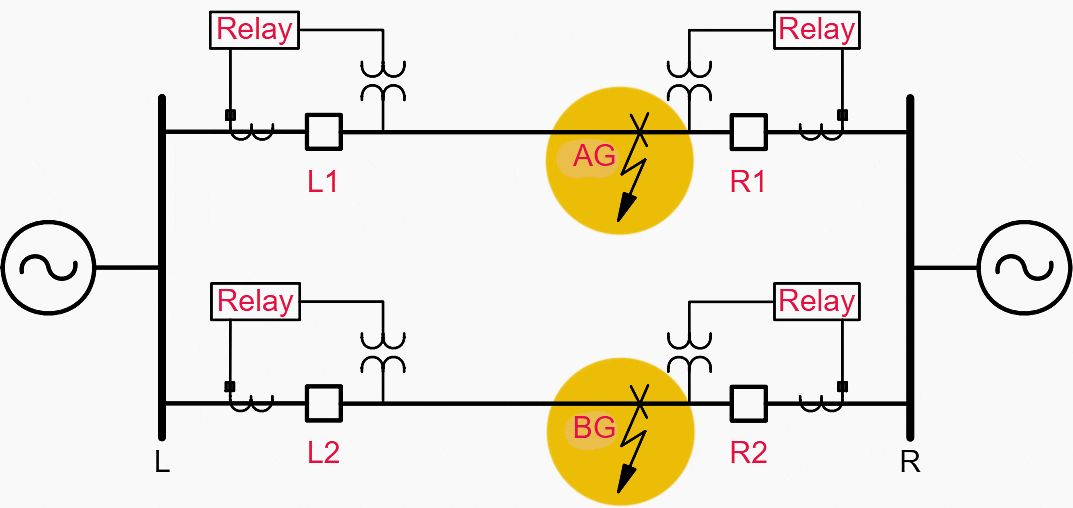

In a simple pilot scheme, the faults depicted in Figure 8 may result in correct single-phase tripping by the relays at R1 and R2 but incorrect three-phase tripping by the relays at L1 and L2. This is because the pilot channel information is two-state only – either the relays see a fault or they do not see a fault. The faulted phase selection is performed by the local relays.
In this example, the relays at L1 and L2 select an ABG fault type resulting in a three-phase trip for a single-line-to-ground fault.
Several approaches may be employed to avoid this misoperation:
Approach #1 – The pilot tripping can be delayed long enough to allow the Zone 1 elements at Bus R to initiate single-phase tripping. After the breakers at Bus R open the proper faulted phases, the relays at L1 and L2 also select the correct phases to trip.
Approach #2 – Multiple two-state pilot communication channels can be used to transmit phase identification in addition to trip permission.
Approach #3 – A digital relay-to-relay communications channel can be used to transmit multiple bits of the actual faulted phase selection in addition to the permissive signal.
The inclusion of a direct transfer trip (DTT) bit and a reclose-blocking bit in the same digital message improves the breaker failure function and prevents reclosing into a faulted breaker. The pilot digital communications channel provides superior performance when compared to traditional communication channels regarding security, availability, and speed.
Availability can be improved more than 20% by adding a simple digital relay-to-relay communications channel in existing installations that use tone equipment to key PTs.
Go back to the Contents Table ↑
7. Three-Terminal Line Protection Application
Consider the system in Figure 9 in which a Permissive Overreaching Transfer Trip (POTT) scheme is applied using traditional frequency shift audio tone communication equipment and independent communication paths between Terminals R, S, and T. Tripping is initiated if the local relay detects a fault, and a PT signal is received from each remote terminal.
In three-terminal line pilot protection applications, where high-speed tripping is essential, loss of a communication channel between any two of the three terminals renders the highspeed pilot protection inoperable, and tripping occurs by time-delayed Zone 2 elements.
For example, if communication is lost between Terminals S and T during an internal fault, Terminal R will high-speed trip and send a DTT to Terminals S and T to clear the fault.
Echo keying logic is included in a Permissive overreaching transfer trip (POTT) scheme at a weak terminal to allow high-speed tripping at a strong terminal if forward tripping elements do not operate at the weak terminal for an internal fault or as an alternative to an open breaker keying signal.
Figure 9 – Three-terminal system with independent communication paths for protection
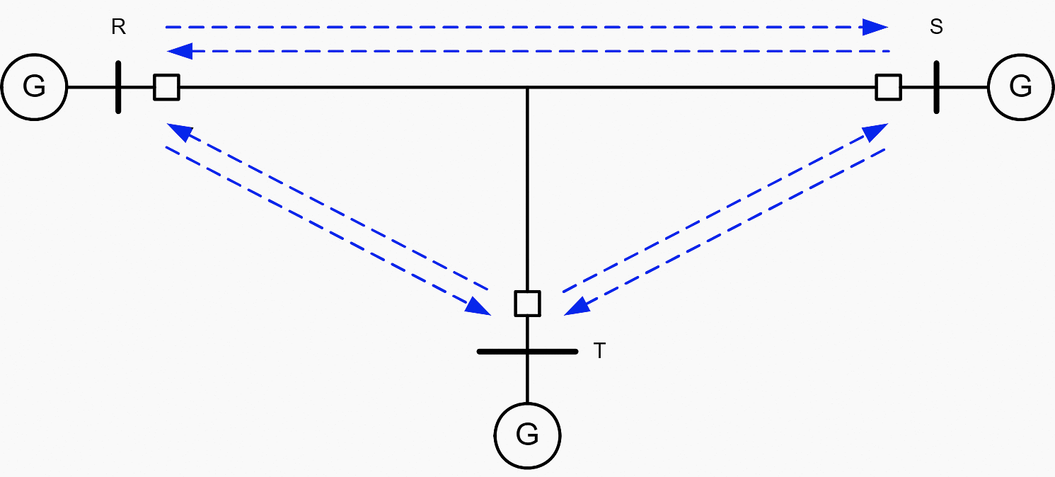

Echo keying logic will only repeat the received PT signal when the PT bit is asserted. In a three-terminal line application, PT is asserted only if the local relay receives a PT signal from both of the remote relays.
In other words, at least two relays must see the fault in order for the PT signal to be repeated. If there is only one weak terminal, the echo keying logic will function as desired. However, if there are two weak terminals, then the echo keying logic will not function if the overreaching PT elements operate only at the strong terminal.
When there are two weak terminals on the line, one can use logic control equations to implement an echo keying logic that also functions when only one PT signal is received.
Go back to the Contents Table ↑
8. Relay-to-Relay Communications Application
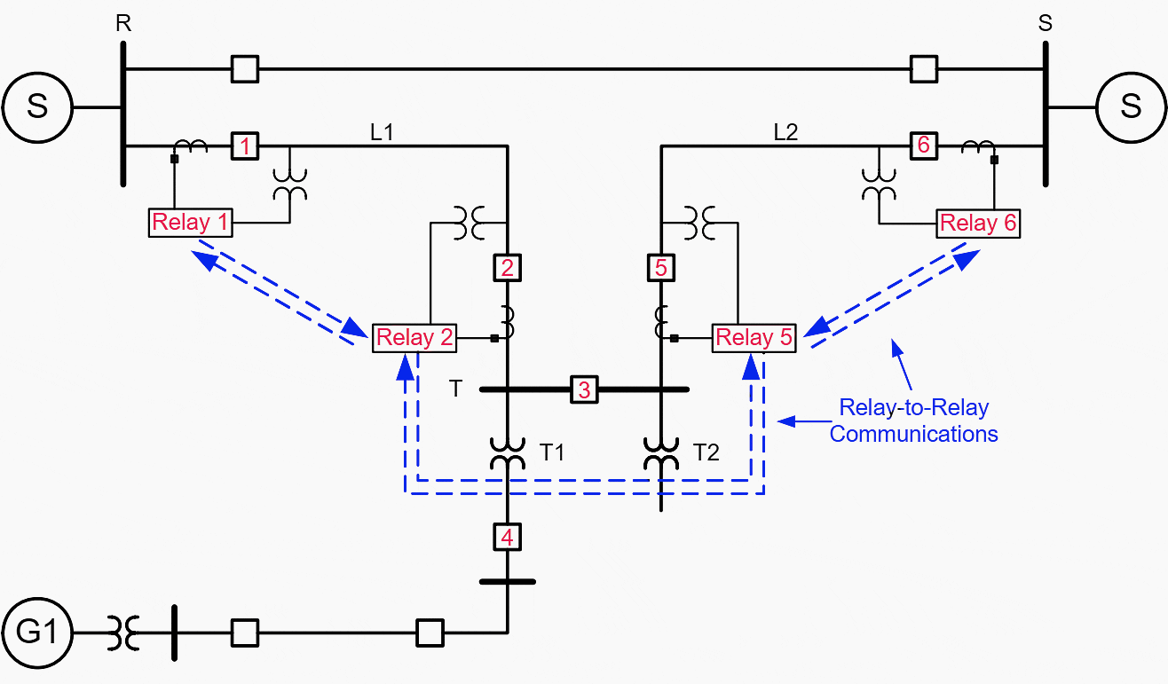
Consider Figure 10 in which a fault occurs inside Transformer T1 and Breaker 2 fails to trip at Station T. For this fault, Breaker 1 at Station R must open due to the breaker failure condition of Breaker 2 at Station T and not be allowed to reclose.
In a traditional protection scheme, a separate DTT is applied between Stations R and T to perform the above function. Relay-to-relay communications between relays of L1 and L2, in conjunction with relay programmable logic, can be used to send a DTT from Station T to Stations R and S during breaker failure conditions at Station T and block reclosing at the remote stations.
For this scenario, using relay-to-relay communications and programmable logic, we can design a protection scheme at Station T to detect L2 tripping at the remote Terminal S, block highspeed reclosing of Breaker 2 at Station T, and transmit a reclose blocking bit to block high-speed reclosing of Breaker 1 at Station R.
Slow-speed reclosing from Station R followed by Breaker 2 closing at Station T with synchronism check and slip-frequency supervision allows the two systems to parallel and improves system reliability.
Figure 10 – Relay-to-relay communications application

Other applications of relay-to-relay communications include:
- Automated relay settings group changes that adjust the distance reach to better handle the mutual coupling effect of parallel lines in the event one circuit is taken out of service for maintenance, and safety grounds have been applied at both line ends.
- Settings group changes to adjust the distance protection reach in the event a breaker is opened for maintenance on a three-terminal line protection application that removes the infeed from that terminal.
- Automatic station restoration schemes that can be implemented using the ability to exchange eight bits of information between relays without the need to utilize additional equipment such as programmable logic controllers.
Suggested Reading – What will happen to digital substations once the internet drops dead? Aftermaths and solutions.
What will happen to digital substations once the internet drops dead? Aftermaths and solutions.
Go back to the Contents Table ↑
Source: Modern distance protection functions and applications by Working Group B5.15, Cigre


Great content and information here
Thank you, Owen.