
Estimated Study Time: 9 minutes
Primary and backup relays
Primary relays operate for a fault in their zone of protection in the shortest time and remove the fewest system elements to clear the fault. On the other hand, backup relays operate in the event that the primary relays fail. Backup relays can be local or remote. Our interest here is in a subset of local backup relays, referred to as breaker failure relays.
 How breaker failure relaying works? (photo credit: NSS Ltd.)
We will now consider this important topic in greater detail. Figure 1 shows a simple representation of lines and transformers around a bus. For the moment, we have shown one circuit breaker per line or transformer.
Later on, we will consider the variations in breaker failure needed to accommodate different types of buses.
A fault at F on line B–C should be cleared by primary relays Rbc and Rcb and their respective circuit breakers. Now consider the possibility that circuit breaker B1 fails to clear the fault. This failure may be caused by the failure of the primary relays, by the failure of current transformers (CTs) or potential transformers (PTs) providing input to the primary relays, by the failure of the station battery or by the failure of the circuit breaker.
Figure 1 – Breaker failure relaying for circuit breaker B1
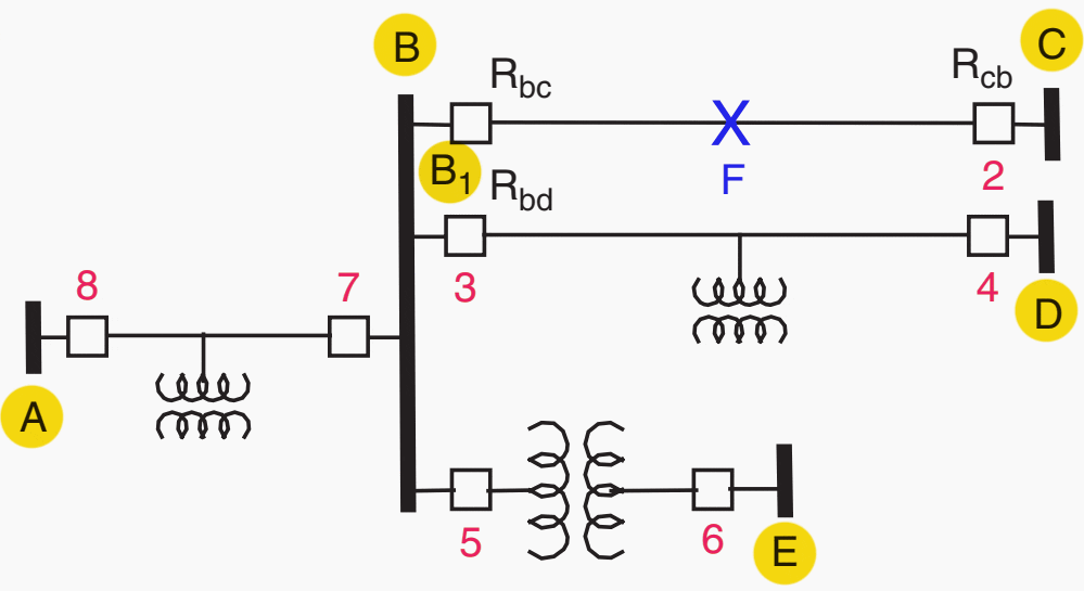
The remote backup function is provided by relays at buses A, D and E to clear the fault F if it is not cleared by circuit breaker B1. However, remote backup protection is often unsatisfactory in modern power systems.
First, it must be slow enough to coordinate with all the associated primary relays. Thus, the remote backup function at bus A must coordinate with the zone 2 relays of lines B–C, B–D and the transformer B–E. Second, because of the possible infeeds at the remote stations, it may be difficult to set the remote backup relays to see fault F from stations A, D and E.
Finally, the power supplied to the tapped loads on lines A–B and B–D is unnecessarily lost due to remote backup operation. A preferred method of protection against the failure of the primary relays at stations B and C is to provide a second set of relays at these locations, represented by R‘bc at station B in Figure 2.
Figure 2 – Primary, backup and breaker failure relays in a single-bus, single-breaker scheme

These relays operate more slowly than Rbc and Rcb, but trip the same circuit breakers. They cover the failure of the primary relays and their associated CTs, the secondary windings of the associated PTs and, as shown in Figure 3, the DC distribution circuit of the primary relays.
However, relays R‘bc do not cover the failure of the circuit breakers themselves.
In the above Figure 1, for example, breakers 3, 5 and 7 would be tripped by the breaker failure relays. Subsequent developments6 replaced the independent relay with the control circuitry shown in Figure 3.
In this scheme, any relay or switch which initiates a trip starts a timer known as the breaker failure timer. The timer is supervised (i.e. controlled) by an overcurrent relay (50-1), which drops out when the current through the breaker goes to zero. If this does not happen for any reason, the timer times out and energizes the lockout relay 86-1, which trips and locks out the circuit breakers 3, 5 and 7.
Figure 3 – DC distribution for primary, backup and breaker failure relays
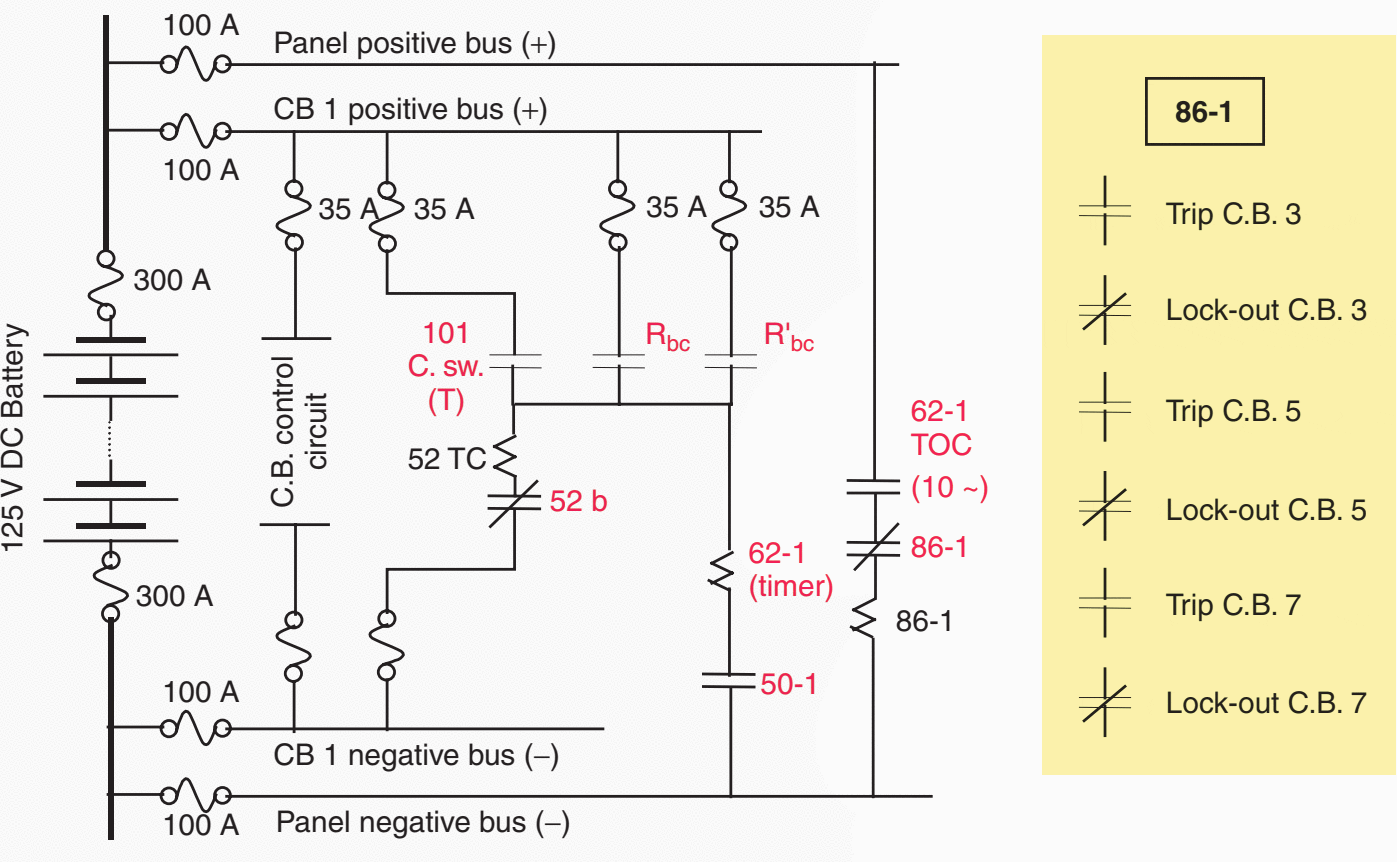
The earliest designs of the circuit breaker failure logic used a breaker auxiliary switch in place of the overcurrent relay. This switch is operated by mechanical or hydraulic linkages and is designed to mimic the main contacts of the circuit breaker.
However, the auxiliary switch has been found to be an unreliable device, especially when the circuit breaker itself is experiencing difficulties in clearing the fault, a condition for which the breaker failure relaying is supposed to provide a remedy. The mechanical linkages may break, the auxiliary switches or the main contacts may be frozen, or for some reason become inoperative while the main set of breaker contacts continues to function normally.
The most common example of this condition (when there is no fault current to be interrupted) is the trip initiated by turbine or boiler controls. Abnormalities in the pressure or temperature of the boiler, or some other mechanical critical element of the boiler-turbine system, may require that the station breaker be tripped, and in such cases, it would be improper to use an overcurrent detector to supervise the breaker failure protection.
The setting of the breaker failure timer
The setting of the breaker failure timer is determined by two constraints. The minimum time must be longer than the breaker clearing time, plus a margin of safety. Since the breaker failure timer does not start until a tripping relay (or switch) has initiated the trip, the operating time of the tripping relay is not a factor in determining the timer setting.
This technical article is centred upon the simple single-bus, single-bus arrangement. In reality, for other bus arrangements, a more involved procedure is required. This is explained in the following example.
Recommended Course
This is an intermediate to advance level course dedicated to schematics and control wiring diagrams of high-voltage and medium-voltage circuit breakers (applicable to power substations, switchyards, power plants, etc.). 39 lessons in 7h 14min total course length.
Learn to Read and Analyze Circuit Breaker Schematics and Control Wiring Diagrams
Source: Power System Relaying by Stanley H. and Arun G.
Related electrical guides & articles


Edvard Csanyi
Hi, I'm an electrical engineer, programmer and founder of EEP - Electrical Engineering Portal. I worked twelve years at Schneider Electric in the position of technical support for low- and medium-voltage projects and the design of busbar trunking systems.I'm highly specialized in the design of LV/MV switchgear and low-voltage, high-power busbar trunking (<6300A) in substations, commercial buildings and industry facilities. I'm also a professional in AutoCAD programming.
Profile: Edvard Csanyi

Very useful information for use in power system protection.
I desire being a member as doing that will help me develop the requisite technical skills to make me proficient in the electricity industry where work.