Comparison of bus configurations
This technical article explains six most common bus configurations used for distribution, transmission, or switching substations at voltages up to 345 kV. Presented single line diagrams and layouts are generalized since they depend on the type and voltage(s) of the substations.

The physical size, type, and arrangement of major equipment, such as power transformers, power circuit breakers, and switches, may cause variance in the layouts to suit individual requirements.
It is important that the engineer’s plans remain as flexible as possible during substation layout to allow for unforeseen difficulties as designs progress. Coordinate activities with the equipment manufacturers to ensure that each design detail reflects the actual equipment to be used.
- Single Bus
- Sectionalized Bus
- Main and Transfer Bus
- Ring Bus
- Breaker-and-a-Half
- Double Breaker-Double Bus
- Cost comparison
1. Single Bus
A single bus configuration consists of one main bus that is energized at all times and to which all circuits are connected. This arrangement is the simplest, but provides the least amount of system reliability.
Bus faults or failure of circuit breakers to operate under fault conditions results in complete loss of the substation. The single bus configuration can be constructed by using either low- or high-profile structures.


Figure 1 illustrates the single bus arrangement with low-profile structures and presents a neat, orderly plan.
The high-profile design, shown in Figure 2, accomplishes the same purpose and may not require as large a site for a given system voltage.
The high-profile configuration can easily be modified to provide this feature by installing group-operated switches and the associated buswork and connections in the positions shown in Figure 2.
This arrangement, however, results in loss of overcurrent protection for the circuit except by remote circuit breakers during the bypassing operations.
A fault occurring on the line with the breaker bypassed would result in complete substation shutdown. The low-profile arrangement does not allow for future addition of this type of bypassing equipment.
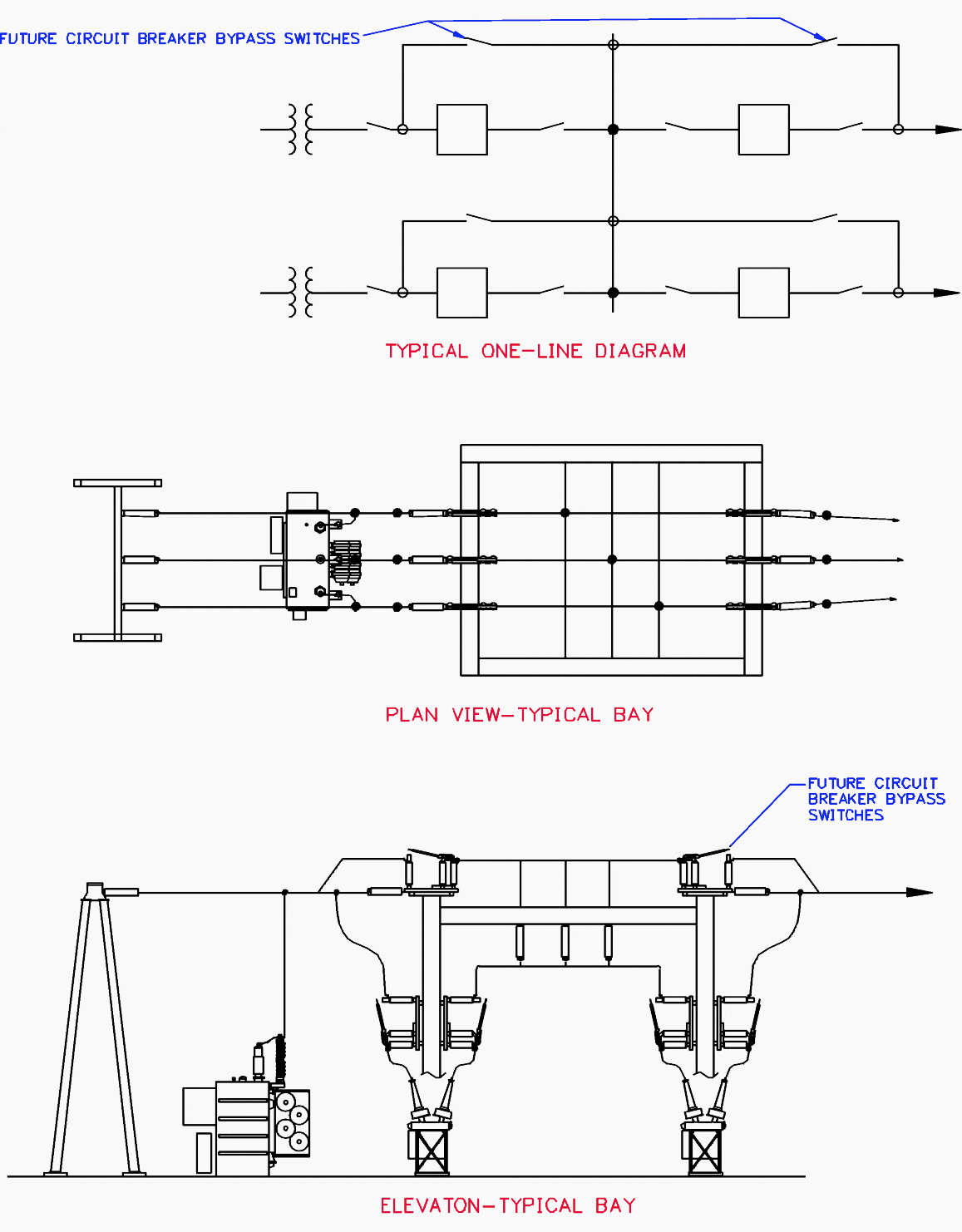

Consequently, in both low-profile and some high-profile substations, the bypass facilities can be installed outside the substation. Switches can be provided that, when closed, parallel two lines to enable one circuit breaker to be removed from service. The other breaker then protects both circuits.
If this bypassing method is used, the equipment associated with both circuits, have to be capable of carrying the total load of both circuits. If the load is greater than the equipment capability, the load should be reduced.
This method of circuit breaker bypassing may be more desirable in high-profile arrangements than that shown in Figure 2 for lines where frequent or lengthy equipment maintenance is expected.
1.1 Advantages
- Lowest cost.
- Small land area required.
- Easily expandable.
- Simple in concept and operation.
- Relatively simple for the application of protective relaying.
1.2 Disadvantages:
- High-profile arrangement equipped with circuit breaker bypass facilities does not provide for circuit protection when bypass facilities are being used inside the substation.
- A single bus arrangement has the lowest reliability.
- Failure of a circuit breaker or a bus fault causes loss of the entire substation.
- Maintenance switching can complicate and disable some of the protective relay scheme and overall relay coordination.
- Maintenance at the upper elevations of high-profile arrangements necessitates de-energization or protection of the lower equipment.
2. Sectionalized Bus
An extension of the single bus configuration is the sectionalized bus arrangement shown in Figure 3. This arrangement is basically two or more single bus schemes, each tied together with bus sectionalizing breakers.
The sectionalizing breakers may be operated normally open or closed, depending on system requirements. In this arrangement, a bus fault or breaker failure causes only the affected bus section to be removed from service and thus eliminates total substation shutdown.
Usually, the fault can be isolated and non-faulted portions of the system restored to service easier and faster because of the increased flexibility of this arrangement.
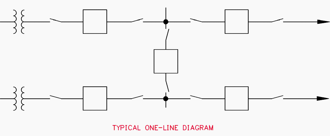

Physically, the equipment can be organized similar to that shown in Figures 1 and 2 for the single bus arrangement.
The sectionalizing breakers and their associated isolation switches are located in line with the main bus. In the high-profile configuration, it is usually desirable to provide a separate bay for the sectionalizing breakers and switches to facilitate maintenance and removal.
The arrangement of lines and transformers in a sectionalized bus arrangement depends on system operating criteria. They should be arranged so as to prevent outage of lines or other circuits dependent on each other.
Bypassing arrangements for the sectionalized bus configuration can be provided as explained for the single bus scheme.
2.1 Advantages
- Flexible operation.
- Higher reliability than single bus scheme.
- Isolation of bus sections for maintenance.
- Loss of only part of the substation for a breaker failure or a bus fault.
2.2 Disadvantages
- A sectionalized bus arrangement has a higher cost than a single bus scheme.
- Additional circuit breakers are required for sectionalizing.
- Sectionalizing may cause interruption of non-faulted circuits.
3. Main and Transfer Bus
A main and transfer bus configuration consists of two independent buses, one of which, the main bus, is normally energized. Under normal operating conditions, all incoming and outgoing circuits are fed from the main bus through their associated circuit breakers and switches.
The bypass switch for the circuit breaker to be isolated is closed, the bus tie breaker and its isolation switches are closed, and the bypassed breaker and its isolation switches are opened to remove the breaker from service. The circuit is then protected by the bus tie breaker.


Figure 4 illustrates a main and transfer bus configuration in a low-profile arrangement. For comparison, Figure 5 shows the same switching scheme with high-profile box-type structures.
With the box-type structure arrangement, two circuit positions can be accommodated per equipment bay.
However, with the low-profile arrangement, each circuit requires its own bay and, as a result, somewhat more land area may be required. When the low-profile configuration is used, equipment bays should be limited in width to a maximum of two bays before the bay-to-bay centerline spacing is increased to accommodate circuit breaker maintenance and removal.
Without the additional space, these tasks can become very difficult.


The high-profile, box-type structure arrangement shown in Figure 5 can accommodate multiple circuits in a relatively small area. The configuration is particularly suitable in environmentally shielded or otherwise isolated locations, where only a limited substation site is available.
This arrangement is generally limited to distribution and subtransmission voltage levels. At transmission voltage levels, independent structures and strain bus interconnections can be used.
3.1 Advantages
- Accommodation of circuit breaker maintenance while maintaining service and line protection.
- Reasonable in cost.
- Fairly small land area.
- Easily expandable.
3.2 Disadvantages
- An additional circuit breaker is required for bus tie.
- Since the bus tie breaker, have to be able to be substituted for any line breaker, its associated relaying may be somewhat complicated.
- Failure of a circuit breaker or a bus fault causes loss of the entire substation.
- Somewhat complicated switching is required to remove a circuit breaker from service for maintenance.
4. Ring Bus
A ring bus configuration is an extension of the sectionalized bus arrangement and is accomplished by interconnecting the two open ends of the buses through another sectionalizing breaker.
This results in a closed loop or ring with each bus section separated by a circuit breaker. For maximum reliability and operational flexibility, each section should supply only one circuit.
For a breaker failure, the two breakers on the sides of the affected breaker open, along with a transfer trip to a remote breaker, to isolate the failed breaker and remove two bus sections from service.
The ring bus arrangement provides for circuit breaker maintenance since any breaker can normally be removed from service without interruption of service to any circuits.
As a result, separate circuit breaker bypass facilities are not required.
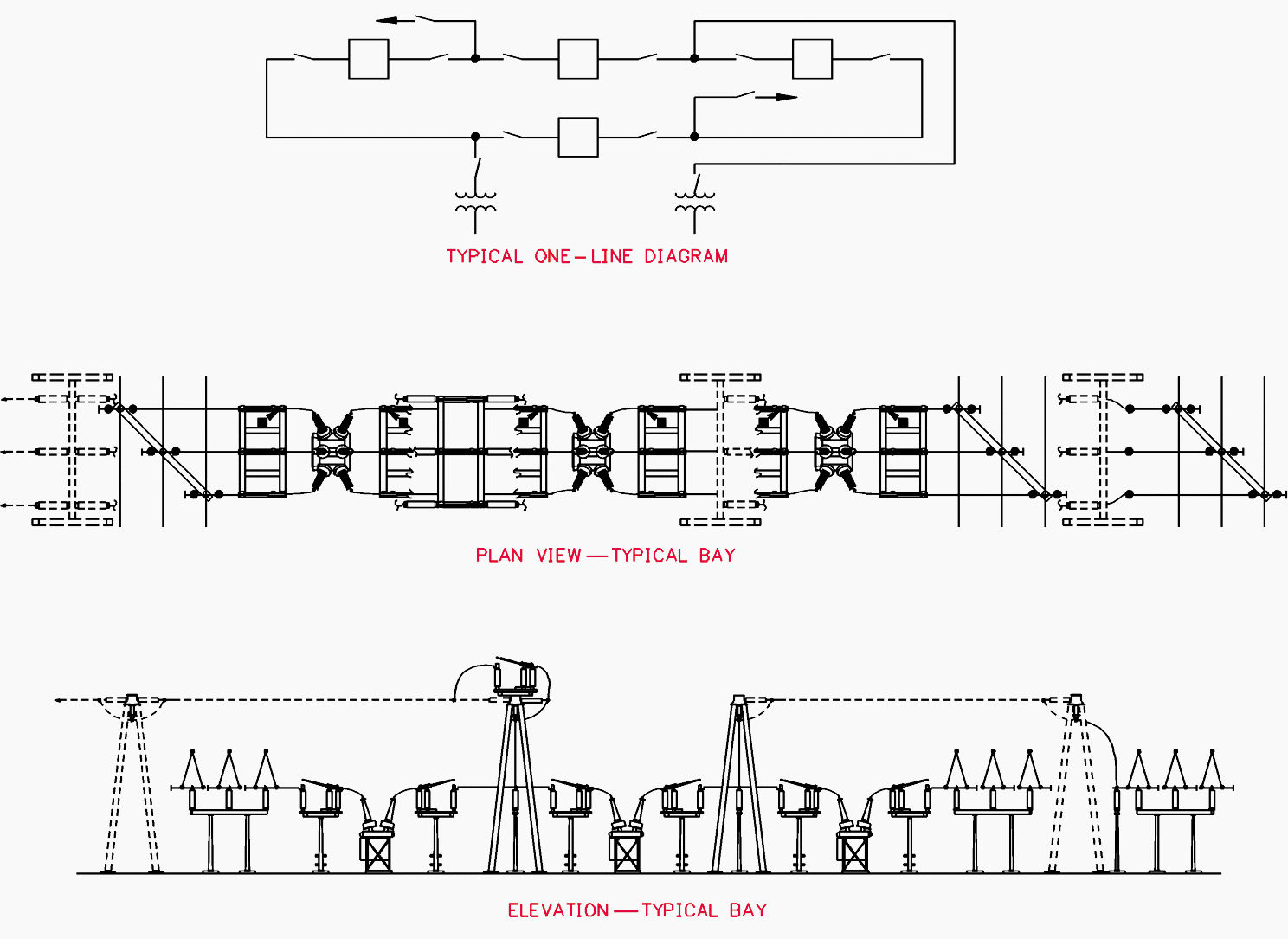

A number of equipment arrangements may be used to provide a ring bus configuration, depending on anticipated substation expansion and possible system modifications. Figure 6 illustrates a typical ring bus configuration.
The arrangement shows four circuit positions, which is a practical maximum for a ring bus configuration. Rather than expanding the ring bus to accommodate additional circuits, other more flexible and reliable configurations, such as the breaker-and-a-half scheme, can be adopted.
Bay centerline spacing should be carefully planned to permit equipment maintenance and removal.
4.1 Advantages
- Flexible operation.
- High reliability.
- Isolation of bus sections and circuit breakers for maintenance without disrupting circuit operation.
- Double feed to each circuit.
- No main buses.
- Expandable to breaker-and-a-half configuration.
- Economic design.
4.2 Disadvantages
- Ring may be split by faults on two circuits or a fault during breaker maintenance to leave possibly undesirable circuit combinations (supply/load) on the remaining bus sections. Some consider this, however, to be a second contingency factor.
- Each circuit has to have its own potential source for relaying.
- This configuration is usually limited to four circuit positions, although larger rings are in service, including 10-position ring buses.A 6-position ring bus is usually considered as a maximum limit for the number of terminals in a ring bus.
- This is a more involved relay scheme since each breaker has to respond to faults on two circuits.
- Automatic reclose schemes may be complex.
5. Breaker-and-a-Half
The breaker-and-a-half configuration consists of two main buses, each normally energized. Electrically connected between the buses are three circuit breakers and, between each two breakers, a circuit as diagrammed in Figure 7.
The breaker-and-a-half configuration provides for circuit breaker maintenance, since any breaker can be removed from service without interrupting any circuits.
Additionally, faults on either of the main buses cause no circuit interruptions. Failure of a circuit breaker results in the loss of two circuits if a common breaker fails and only one circuit if an outside breaker fails.
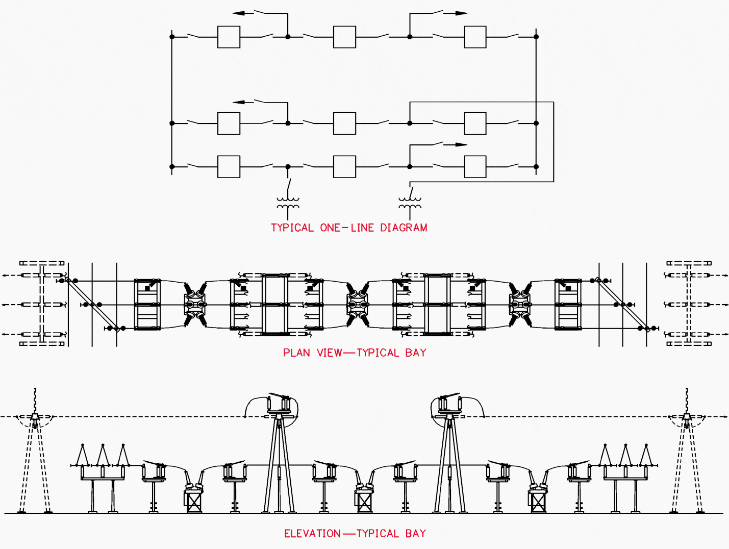

A typical bus configuration for a breaker-and-a-half arrangement is shown in Figure 7. This is the same basic equipment assemblage as described for the ring bus scheme.
Bay centerline spacing should be carefully planned to permit equipment maintenance and removal.
5.1 Advantages
- Flexible operation.
- High reliability.
- Can isolate either main bus for maintenance without disrupting service.
- Can isolate any circuit breaker for maintenance without disrupting service.
- Double feed to each circuit.
- Bus fault does not interrupt service to any circuits.
- All switching done with circuit breakers.
5.2 Disadvantages
- One-and-a-half breakers are required per circuit.
- Relaying is involved, since the center breaker has to respond to faults of either of its associated circuits.
- Each circuit should have its own potential source for relaying.
6. Double Breaker–Double Bus
The double breaker-double bus configuration consists of two main buses, each normally energized. Electrically connected between the buses are two circuit breakers and, between the breakers, one circuit, as diagrammed in Figure 8.
Two circuit breakers are required for each circuit.
A typical bus configuration for a double breaker–double bus arrangement is shown in Figure 8.
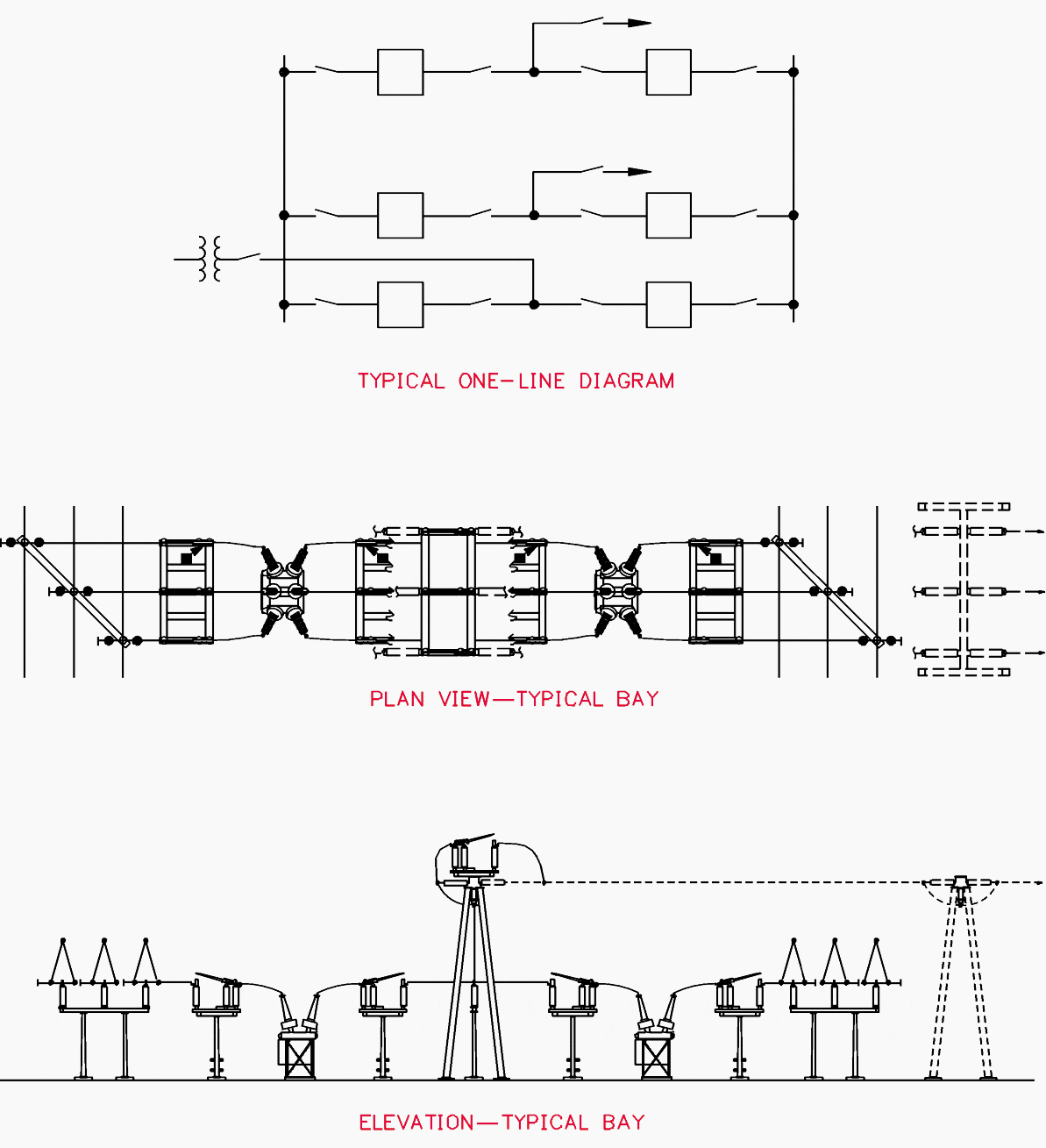

Use of the double breaker–double bus configuration is usually limited to large generating stations because of the high cost. The additional reliability afforded by this arrangement over the breaker-and-a-half scheme usually cannot be justified for conventional transmission or distribution substations.
Occasionally, at a generating station, one bay of a breaker-and-a-half arrangement is used as a double breaker–double bus arrangement for a generator terminal to provide equal access to either main bus.
6.1 Advantages
- Flexible operation.
- Very high reliability.
- Isolation of either main bus for maintenance without disrupting service.
- Isolation of any circuit breaker for maintenance without disrupting service.
- Double feed to each circuit.
- No interruption of service to any circuits from bus fault.
- Loss of only one circuit for breaker failure.
- All switching with circuit breakers.
6.2 Disadvantages
- This configuration carries a high cost.
- Two circuit breakers are required for each circuit.
Relative Switching Scheme Costs
The selection of a station switching scheme is the result of the evaluation of many factors, including such intangibles as personal preference and judgment. Whatever arrangement is finally selected should meet all known or anticipated requirements, such as operating and maintenance criteria, future expansion, and reliability.
To assist in the evaluation, Table 1 provides a reasonable measure for the basis of economic comparison.
Table 1 – Switching Scheme Cost Comparison
| Switching Scheme | Approximate Relative Cost COmparison |
| Single Bus | 100% |
| Sectionalized Bus | 122% |
| Main and Transfer Bus | 143% |
| Ring Bus | 114% |
| Breaker-and-a-Half | 158% |
| Double Breaker–Double Bus | 214% |
The comparison is based on four-circuit low-profile arrangements with power circuit breakers in all circuits. Power transformer costs are not included. In schemes utilizing other protective devices or different circuit quantities, the relative costs may vary from those listed.
Prepare detailed construction estimates for all schemes under consideration.
Source: Design Guide for Rural Substations by United States Department of Agriculture




I believe the one-line diagram you show in Figure 2 may be incorrect.
Shouldn’t the tap to the bypass line be directly off the transformer secondary, instead of tapping off the ‘load’ (circuit breaker) side of the first disconnect? In the configuration shown, you would not be able to energize the bypass without energizing the line side of the CB, thereby making it impossible to remove from service.
I stand to be corrected, and welcome any corrections / information, as I am not a HV expert.
Thanks for the technical information. Pls can you send PDF version to my mail?
Would you please send a pdf to my email
Thanks
It is very nice information
Full PDF sharing is high appreciated
Appreciate your technical information.
hi very nice. can i get a pdf for me too pleases
Such a very educative guide. Please can I get a pdf copy of it? Thanks
Thank you very much…
The terrific explanation I have ever read.
Thanks so much
Can I get a logic where i have to operate Auto reclosure in main and TBC breaker from the single distance protection relay.
Thanks, but please make pdf for your lectures.
I am very happy with your contributions to my skills but please can I able to get PDF to my e-mail