Bus protection relays
When selecting relays for bus protection, a major concern is the ability of the protective relaying scheme to restrain from tripping for close-in line faults. Tripping for bus faults, the reason for installing bus differential relaying, is less of a concern. During fault testing conditions, line circuit breakers, rather than bus sectionalizing circuit breakers or bus tie circuit breakers, should be closed to test bus integrity.
Bus differential, which is the most sensitive and reliable method for protecting a substation bus, is installed at transmission and distribution substations and switchyards. Overcurrent protection may be used for bus protection at lower voltage substations.

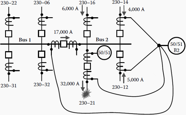
During the initial development of power systems, substation buses were protected with overcurrent differential relays as illustrated in Figure 1. CTs are connected so that relays respond to the difference between incoming and outgoing current. But, since the possibility of CT saturation cannot be eliminated for close-in line faults, overcurrent differential relays are delayed to coordinate with transmission- or distribution-line protection.
For a close-in fault on the 230-21 line, the assumption is that busside CTs (connected to line relays) operate as designed, but that the line-side CTs (connected to the bus differential relay) saturate and that overcurrent bus differential relays must be coordinated with the line relaying.
The instantaneous overcurrent bus differential relays initiate timers and the time overcurrent bus differential relays are coordinated with line relays. (Overcurrent bus differential relays are unacceptable if instantaneous clearing of bus faults is required.)
If overcurrent relays with the settings and characteristics shown below are used to protect the 230-21 line, overcurrent bus differential relay settings could be determined as follows:
230-21 Line
TOC (51) Phase: TOC (51G) Ground:
– 5 Relay Amps, 800 Line Amps 1 Relay Amp, 200 Line Amps
– #5 time dial, Inverse #6 time dial, Extremely Inverse
IOC (50) Phase: IOC (50G) Ground:
– 20 Relay Amps, 4000 Line Amps 15 Relay Amps, 3000 Line Amps
Bus Differential
TOC (51) Phase: Extremely Inverse
– Definite TOC Phase, Quick Trip
SOURCE: Unknown, Chapter 16 – Bus Protection


The good works you’re doing and presenting to audience free of charge makes a big difference. I much more appreciate and showy big respect to this
it’s really nice to know you Edvard, I am also going to complete my bachelor’s courses in Electrical and electronics engineering.