
Estimated Study Time: 18 minutes
How to detect busbar faults?
In the olden days, the clearance of busbar faults was done by time-delayed distance relays or overcurrent relays, resulting in an extension of fault for a longer duration of time. In the present day’s networks, which are highly interconnected, having numerous infeeds and consisting of line sections of varying lengths, clearance of bus faults in zone-2 or zone-3 of a distance relay cannot be tolerated.
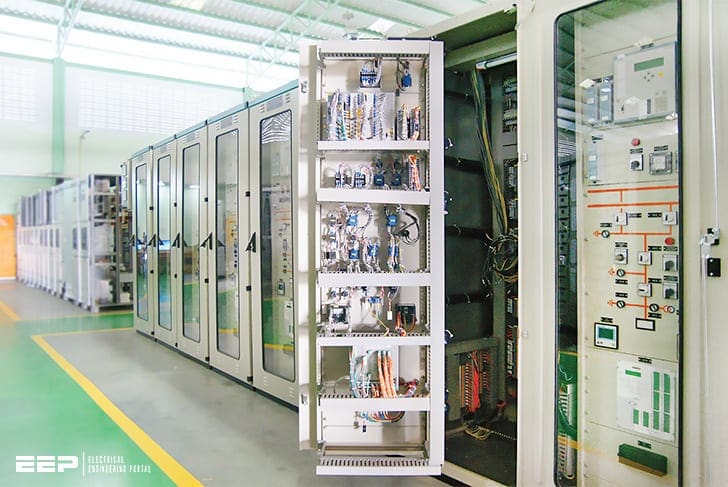 Principles and applications of busbar protection schemes (you SHOULD know about) - photo credit: MANTRA SWITCHGEAR CO.,LTD.
Also, selective tripping becomes a problem on installations having different bus sections. In order to maintain the system stability and minimize fault damage due to high fault levels, time-delayed tripping for busbar faults is no longer acceptable.
It is, therefore, necessary to detect busbar faults selectively with a unit form of the protection scheme.
Busbar protection scheme should possess the following:
- It should be completely reliable
- It should be absolutely stable under all types of severe through fault conditions.
- It should provide discrimination between sections of the bus bars to ensure that circuits connected to the fault busbar alone are isolated
- It should be of high-speed protection so as to minimize damage and maintain system stability
Advantages of Breaker and a half arrangement:
- It has 3 breakers for two connections. Each circuit is connected to a particular bus.
- No changeover of the line from one bus to the other is required.
- This pairing is done such that one is a source and the other a load.
- For breaker maintenance of any line, the load gets transferred to the other bus.
- On the occurrence of a bus fault or for maintenance all the interconnections will be on the healthy bus.
- Even if both buses become dead, lines can still be in service through the tiebreakers.
- Busbar protection methods (example of 400 kV system)
- Busbar protection schemes: Principles and Applications
- Testing of busbar protection
1. Busbar protection methods (example of 400 kV system)
Generally, the 400 KV Substations are provided with breaker and half arrangement. In breaker and half scheme, five CTs method or four CTs method will be adopted for protection.
1.1 Five CTs Method
The CTs arrangement is shown in the figure for 5 CTs method in breaker and half scheme:
- Line side CTs will be utilized for Line Protection
- Bus side CTs will be utilized for bus protection.
- Teed Protection will be used to cover the blind area between bus CTs, Line CTs, and Tie Breaker CT.
- Two differential relays are provided for each T-Section by summating the three concerned CTs i.e. CT1, CT2, and CT5 for T-Section of feeder-1 and CT3, CT4 and CT5 for T-Section of feeder-2.
Go back to Table of Contents ↑
1.2 Four CTs method
The CTs arrangement is shown in the figure for 4 CTs method in breaker and half scheme:
- For feeder protection both bus CT and opposite tie-breaker CT will be summated and connected to the relay (CT1 & CT4 for feeder-1, CT2 & CT3 for feeder-2).
- Bus side CTs will be utilized for bus bar protection.
- There is no uncovered zone in 4 CTs method.
Go back to Table of Contents ↑
2. Busbar protection schemes: Principles and Applications
- High impedance circulating current scheme
- Biased differential or low impedance circulating scheme.
2.1 High Impedance circulating current protection
a) Operating Principles
This is a unit type of protective scheme in which the currents entering and leaving the busbar installations are compared continuously. The objective is to provide fast operation at a low fault setting for internal faults and yet retain stability up to the highest possible value of short circuit current on through faults.
Theoretically, such a system is unaffected by through faults, but in practice, the associated current transformers may not behave ideally when the current exceeds a certain value. Errors in transformation due to saturation on the CT cores may be sufficient to cause mal-operation if special precautions are not taken.
Consider the Figure 3 and Figure 4 above.
Assuming that due to external fault on line X, CT X gets saturated (i.e.) produces no output. This is represented by a short circuit as indicated in Figure 4. This is the worst condition for the relay from a stability point of view since the spill current is maximum. The high impedance principle involves choosing an impedance high enough to stabilize the relay for this worst condition.
Assuming that current Iy flows through the saturated CT only. This will develop voltage Vr given by:
Vr = Iy (Rct + Rlx)
Where:
- Iy = Fault current in Amps,
- Rct = CT secondary resistance
- Rlx = Lead resistance
The relay circuit impedance is then adjusted so that the necessary voltage to operate the relay is greater than the voltage VR.
Vs = Ir × R
Where:
- Vs = Setting voltage
- Ir = Relay current setting
- R = Relay branch impedance
During an internal fault, the CTs will attempt to transform the full fault current and pass this through protection relay circuit. This will be many times the setting current and hence voltage output required from CTs will be of the order of many kVs.
Practically this is not possible and CTs may get saturated. To enable faster operation of the relay, these CTs should have a knee point voltage equal to at least twice the relay setting voltage Vs.
b) Through Fault Stability
The stability limit of the scheme is based on the maximum through fault current. As shown previously, the stability limit is governed by the relay setting voltage. This must not be less than the stability voltage of the system, which is calculated by assuming that maximum through fault current flows through one CT and out through a second one, the latter being the most remote (and hence maximum lead resistance) from the relay associated with the Zone considered.
It is further assumed that the DC component of the offset primary current completely saturates the second CT, while the first one continues to transform perfectly.
c) Check Feature
A second line of defence is considered good practice in most schemes of busbar protection, not to give security against mal-operation of the primary protection, but to prevent incorrect tripping due to damage to wiring and equipment from extraneous sources.
A check feature is provided by duplication of the primary protection using a second set of current transformers on all circuits other than bus section and bus coupler units.
d) Use of Non-linear Resistors
Under internal fault conditions the high impedance relays circuit constitutes an excessive burden to the CTs, leading to development of high voltage. The insulation of CT secondary winding and the relay will not be able to withstand these high voltages, hence it is limited to less than 3 KV peak by use of non-linear resistors called metrosils connected in parallel with the relay circuits.
e) Supervision
When a CT secondary winding or connections between CT and the relay circuit get open circuited, the resultant out of balance current will flow through the parallel combination of the relay, metrosil and the CT magnetizing impedance. This may cause unwanted operation of the relay for load or through faults depending on the effective primary setting.
This condition of an open circuit can be detected by measuring the voltage across the relay circuit by a sensitive voltage operated relay as shown in Figure 5. This relay is set to operate when the out-of-balance current equals about 10% of the least loaded feeder connected to the busbar or 25 amperes, whichever is greater.
When the busbar protection has a fault setting below full load of the connected feeders, it is very likely to operate due to an open circuited current transformer. In this case, a check feature is required to prevent tripping.
At the same time, it is important that the bus wires are short circuited via the supervision relay to prevent thermal damages to the relay and stabilizing resistors which would otherwise remain continuously picked up under load conditions.
The supervision must be time delayed to avoid a false alarm during genuine fault conditions, typically three seconds is adopted.
High impedance busbar protection (VIDEO)
This video introduces the basic principles behind HIGH IMPEDANCE BUSBAR PROTECTION.
Go back to Table of Contents ↑
2.2 Low impedance biased differential relays
Principle
An alternative to the high impedance protection described above is the biased differential relay. This type of protection makes use of the fact that during system conditions that give rise to high spill current (namely, heavy through faults), there is high amount of circulating current as well between the infeeding and out-feeding CT secondaries.
In a biased differential relay, the operating current is arranged to increase proportionally to the load (circulating) current.
Many of the considerations applicable to high impedance schemes are applicable here as well. For example independent check zone in addition to the main zone and supervision element are provided in this scheme.
Go back to Table of Contents ↑
2.3 High impedance vs. Low impedance schemes
High impedance as well as low impedance schemes have their own advantages. Both are well-tried, proven methods of providing protection for the busbar.
The most obvious advantage of a high impedance scheme is the fact that it combines sensitivity to internal faults and stability during through faults. The scheme may be made stable to any through fault level, and yet retain sufficient sensitivity for internal faults withweek infeeds.
As it requires only very nominal current for operation, it can deal with internal faults that result in saturation of the CT. The scheme is simple and straightforward to apply.
A true low impedance scheme has the advantage that it can work with CTs of moderate output compared to a high impedance scheme. The scheme does not impose a high burden on the CT.
A scheme that uses only one core has an inherent disadvantage – its setting must be such that no mal-operation occurs when there is an open circuitry of the CT secondary or the secondary leads. Under this condition, the concerned zone will see an unbalance current equal to the load current flowing in the relevant feeder.
To avoid unnecessary operation of the scheme, the zone settings or the setting of the check relay must be more than the maximum expected load current on any feeder in the substation. Thus, in the case of schemes that utilize only one CT core, the basic sensitivity is poorer than the load
current.
When the scheme involves two CT cores, one feeding the main zone and the other feeding the check zone, the above problem does not arise. Open circuiting will affect only on the zones, and the tripping will not be through since the other zone remains stable. The chances of open circuitry occurring in two CT cores simultaneously is very remote. Hence in such a scheme, setting much lower then load current is possible.
In the same connection, it must be pointed out that schemes have check zone fed off Independent CT cores are clearly superior to schemes that do not have check zones or those that cannot accommodate separate inputs for the main and check zones. First and foremost, a check zone contributes significantly to the security of the scheme.
Go back to Table of Contents ↑
3. Testing of Busbar Protection
A Current source is required to test the Bus bar differential relay. Stability test also conducted on the bus bar differential relay similar to normal differential relay.
Go back to Table of Contents ↑
Sources: Construction and operational practices for EHV substations and lines by APTRANSCO
Related electrical guides & articles


Edvard Csanyi
Hi, I'm an electrical engineer, programmer and founder of EEP - Electrical Engineering Portal. I worked twelve years at Schneider Electric in the position of technical support for low- and medium-voltage projects and the design of busbar trunking systems.I'm highly specialized in the design of LV/MV switchgear and low-voltage, high-power busbar trunking (<6300A) in substations, commercial buildings and industry facilities. I'm also a professional in AutoCAD programming.
Profile: Edvard Csanyi

How and where do you install bus-zone protection when there is no line breaker in the station but the line breaker is on the remote station?
Hi,
500KVA(30/0.415kV) 5 Nos of transformer gives supply (5 input and one output) to Lt Panels, bus bar protection required if all transformer operate parallel which fulfill all //rl operation condition. Please suggest.