Few words about Sub-main circuits
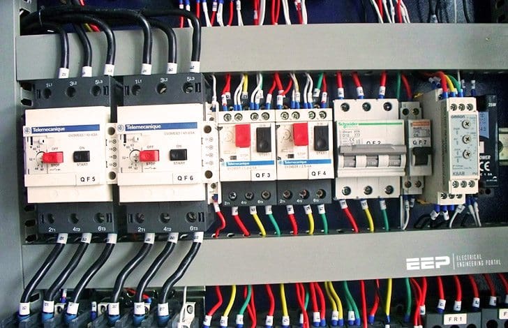
A sub-main electrical circuit can be defined as a circuit connected directly from the main LV switchboard to a sub-main distribution panel or a rising main for final connection of the minor current-using equipment.

The Code requires that the maximum copper loss in every sub-main circuit should not exceed 1.5% of the total active power transmitted along the circuit conductors at rated circuit current.
Similar approach could be followed for sizing conductor as for feeder circuit. However, assumption has to be made in the design for various characteristics of the sub-main circuit including design current, expected harmonic current (THD) in the circuit, degree of unbalance, etc.
Alternatively, an energy efficiency method introduced by the Code could also be used for preliminary cable sizing. This energy efficiency method for cable sizing requires the calculation of the maximum allowable conductor resistance based on the maximum copper loss requirement as stipulated in the code.
For a 3-phase 4-wire circuit (assuming balanced, linear or non-linear):
Active power transmitted via the circuit conductors //
P = √3 · UL · I1 · cosθ
Total copper losses in conductors //
Pcopper = (3 · Ib2 + IN2) · r · L
where:
- UL – Line to line voltage, 380V
- Ib – Design current of the circuit in ampere
- I1 – Fundamental current of the circuit in ampere
- IN – Neutral current of the circuit in ampere
- cosθ – Displacement power factor of the circuit
- r – a.c. resistance / conductor/ metre at the conductor operating temperature
- L – Length of the cable in metre
Percentage copper loss with respect to the total active power transmitted:

Therefore,

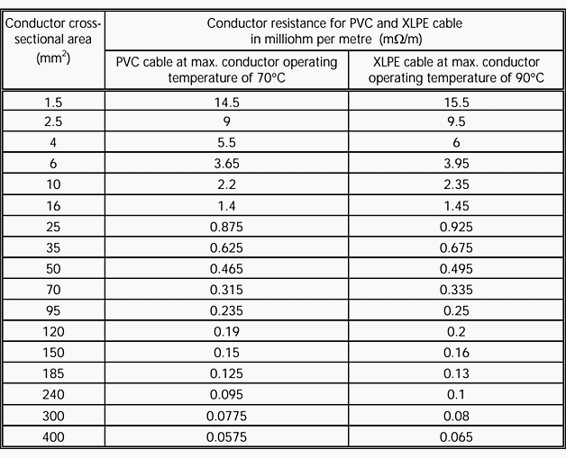
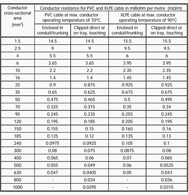
Table 4.2A and 4.2B in the Code provide a quick initial assessment of cable size required for the common cable types and installation methods used in Hong Kong for this example.
The tabulated current rating of the selected cable could then be corrected by applying the correction factors accordingly. The effective-current carrying capacity of the selected cable must be checked so that its value is larger than or equal to the nominal rating of the circuit protective device.
Calculate an appropriate cable size
A 3-phase sub-main circuit having a design fundamental current of 100A is to be wired with 4/C PVC/SWA/PVC cable on a dedicated cable tray. Assuming an ambient temperature of 30°C and a circuit length of 40m, calculate an appropriate cable size for the following conditions:
- CASE 1 // Undistorted balanced condition using traditional method (cosθ = 0.85)
- CASE 2 // Undistorted balanced condition with a max. copper loss of 1.5% (cosθ = 0.85)
Case #1
Undistorted balanced condition using conventional method:
- Ib = 100A
- In = 100A
- It(min) = 100A
Assume the correction factors Ca, Cp, Cg and Ci are all unity.

Refer to BS7671:2008, The Requirements for Electrical Installations,
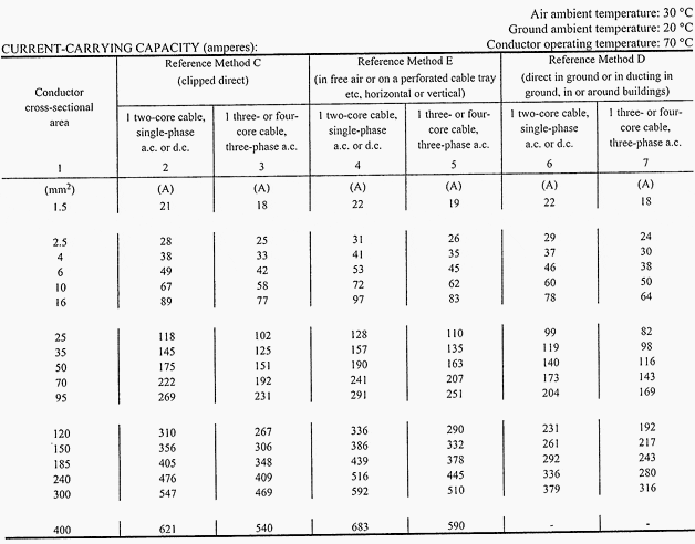
Table 4D4A for 25mm2 – 4/C PVC/SWA/PVC cable – It = 110A
Table 4D4B for r = 1.5mV/A/m x = 0.145mV/A/m (negligible)
| Conductor operating temperature | t1 = 30 + 1002 / 1102 · (70 – 30) = 63°C |
| Ratio of conductor resistance at 63°C to 70°C | r = (230 + 63) / (230 + 70) = 0.98 |
| Voltage drop | u = 1.5mV/A/m · 0.85 · 0.98 · 100A · 40m = 5V (1.3%) |
| Active power transferred (P) | P = √3 · 380V · 100A · 0.85 = 56kW |
| Total copper losses in conductors (Pcu) | = 3 · 1002 A2 · 0.0015Ω/m / √3 · 0.98 · 40m = 1.02kW (1.82%) (Cable size selected is not acceptable if the maximum allowable copper loss is 1.5%) |
Case #2
Undistorted balanced condition with a maximum copper loss of 1.5%
(cosθ = 0.85)
Maximum copper loss method using Table 4.2A in the Code for initial assessment of an approximate conductor size required by calculating the max. conductor resistance at 1.5% power loss:

From Table 4.2A 35 mm2 – 4/C PVC/SWA/PVC cable having a conductor resistance of 0.625mΩ/m is required. Refer to BS7671:2008, The Requirements for Electrical Installations:
Table 4D4A for 35mm2 4/C PVC/SWA/PVC cable It = 135A
Table 4D4B for r = 1.1mV/A/m x = 0.145mV/A/m
| Conductor operating temperature | t1 = 30 + 1002 / 1352 · (70 – 30) = 52°C |
| Ratio of conductor resistance at 52°C to 70°C | r = (230 + 52) / (230 + 70) = 0.94 |
| Voltage drop | u = 1.1mV/A/m · 0.85 · 0.94 · 100A · 40m = 3.5V (0.92%) |
| Active power transferred (P) | P = √3 · 380V · 100A · 0.85 = 56kW |
| Total copper losses in conductors (Pcu) | = 3 · 1002 A2 · 0.0011Ω/m / √3 · 0.94 · 40m = 716kW (1.28%) (Cable size selected is acceptable, i.e. power loss < 1.5%, under undistorted and balanced conditions) |
RELATED TABLES //
TABLE 4.2A
Multicore Armoured and Non-armoured Cables (Copper Conductor), Conductor Resistance at 50 Hz Single-phase or Three-phase a.c.

Resistance at 50 Hz Single-phase or Three-phase a.c.
TABLE 4.2B
Single-core PVC/XLPE Non-armoured Cables, with or without sheath (Copper Conductor), Conductor Resistance at 50 Hz Single-phase or Three-phase a.c.

Single-core PVC/XLPE Non-armoured Cables, with or without sheath (Copper
Conductor), Conductor Resistance at 50 Hz Single-phase or Three-phase a.c.
TABLE 4D4A
Multicore armoured 70C thermoplastic insulated cable

TABLE 4D4B
Voltage drop (per ampere per-metre)

Reference // Code of Practice for Energy Efficiency of Electrical Installations – Electrical and Mechanical Services Department – The Government of the Hong KongSpecial Administrative Region


Hello well calculation, how about distribution transformed cable in 100Kva in secondery side and distance?
Thank you
Dear Sir,
How can I upload data/article at this page.
Best Regards
Md Fazlul Haque
Bangladesh
how do u get the vale of 230 in case of ratio of resistance calculation, please. overall nice article..
Articles are very useful for Project engineers
It means 35mmsq size of L1, L2, and L3, with 16mmsq size of Neutral, and 16mmsq size of Earth Cable.
i am interested on electrical engineering work
Can pls explain me what is mean 3×35+16+16 for the cable size ?
Good article..
The designation of size cable means 3 line with cross section 35, plus neutral and earth cable with 16 mm of cross section..
Kindly regards.
m.Changala
Dear
If the main feeder cable is 70 mm, what is the size of the cable connected between Busbar and Main Circuit Breaker
Regards
Muhammad Kuraan
Ambassador
I’m looking for a 40m supply cable for a distribution board
Good one
I need sample disign for building electrical installation
very good article
it is a very good article
we being in practical electrical training is very usefull
Good article, however would be good to know the table/code reference for the tables. Please comment on references and standard used,, thanks
Please cite the code, chapter & verse(s) being referenced herein. Good examples but I’m not familiar with the tables used. Thank you!
mr. Manuel Bolotinha
i humbly request you to mail me electrical (&other related material whether its electrical or instrumentation or electronics) design & installation material.
regards
mohammed_nizam01@yahoo.com
nics.yahu@facebook.com
Good presentation.
To size a cable, no matter if it is LV a sub-main circuit or not, is also necessary to verify if the cable withstand the thermal stress due to short-circuit current.
The standars on which the tables are based should be indicated (IEC; ANSI/IEEE; BSI; CENELEC?)
I would like to see these articles written in a more professional way, showing all the required calculations and considerations.
Please let me know how I can cooperate with this p+latform and upload articles.
Manuel Bolotinha – Electrical Engineer and Certified Professional Instructor.
i humbly request you to mail me electrical (&other related material whether its electrical or instrumentation or electronics) design & installation material.
regards
mohammed_nizam01@yahoo.com
nics.yahu@facebook.com
Dear E,K. Greetings.Thanks for a very imp.technical info. about data to be considered for selection for sub circuits.
Pl. arrange to e mail such useful tech data for Electrical designs.
Warmest regards.