
Cableways
The term cableways refers to conductors and/or cables together with the means of support and protection, etc. for example cable trays, ladders, ducts, trenches, and so on… are all cableways.
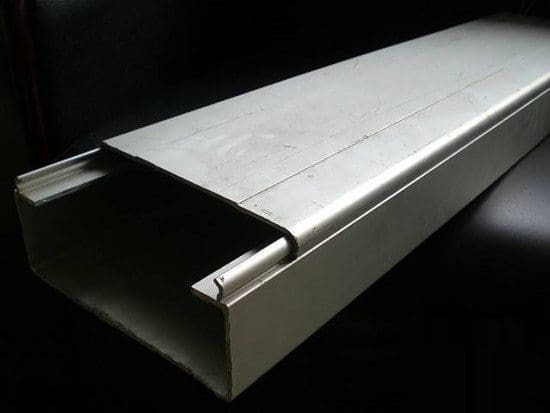
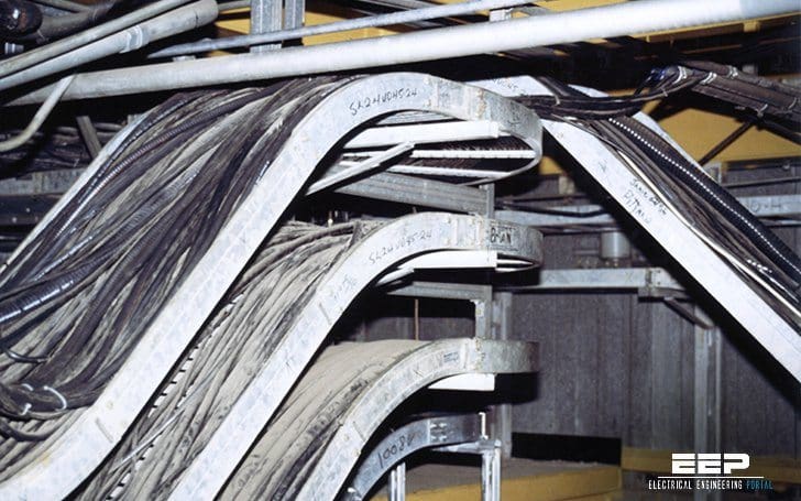 Recommended Practice For Cableways Selection and Installation (on photo: Overcrowded metal cable trays; credit: wikipedia.org)
This technical article covers the following topics:
- Selection of materials and shapes
- Design recommendations
- Metal and non-metal cableways are available
- Implementation of cableways
Selection of materials and shapes
Selection of materials and their shape depends on the following criteria //
- Severity of the electromagnetic (EM) environment along cableways (proximity of sources of conducted or radiated EM disturbances)
- Authorised level of conducted and radiated emissions
- Type of cables (shielded?, twisted?, optical fibre?)
- EMI withstand capacity of the equipment connected to the wiring system
- Other environmental constraints (chemical, mechanical, climatic, re, etc.)
- Future extensions planned for the wiring system
Non-metal cableways are suitable in the following cases:
- A continuous, low-level EM environment
- A wiring system with a low emission level
- Situations where metal cableways should be avoided (chemical environment)
- Systems using optical fibres
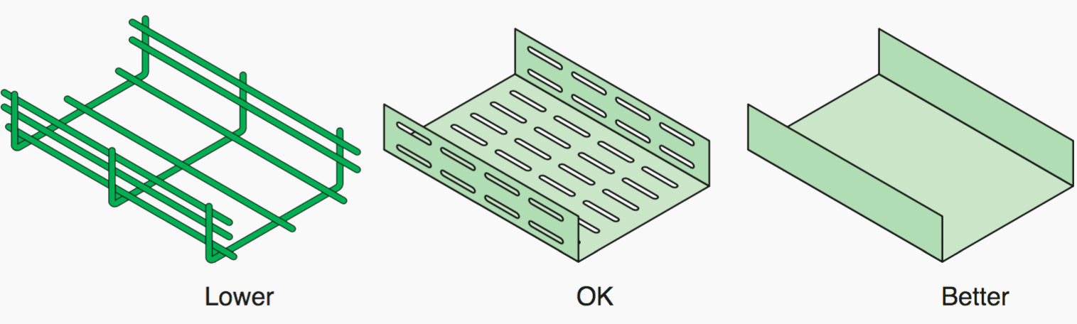
For metal cableways, it is the shape (at, U-shape, tube, etc.) rather than the cross-sectional area that determines the characteristic impedance.
Closed shapes are better than open shapes because they reduce common-mode coupling. Cableways often have slots for cable straps. The smaller the better. The types of slots causing the fewest problems are those cut parallel and at some distance from the cables.
Slots cut perpendicular to the cables are not recommended (see Figure 1).
In certain cases, a poor cableway in EMI terms may be suitable if the EM environment is low, if shielded cables or optical bres are employed, or separate cableways are used for the different types of cables (power, data processing, etc.).
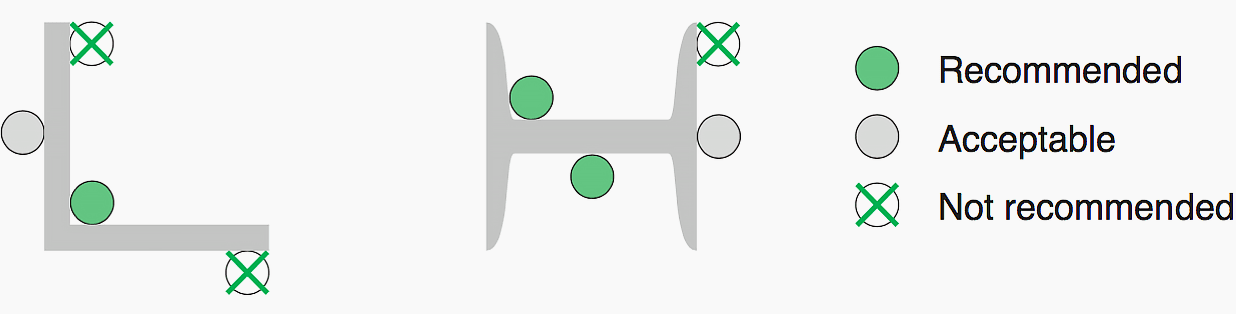
The height of the cables must be lower than the partitions of the cableway as shown below. Covers also improve the EMC performance of cableways. In U-shaped cableways, the magnetic field decreases in the two corners.
That explains why deep cableways are preferable (see Figure 2).
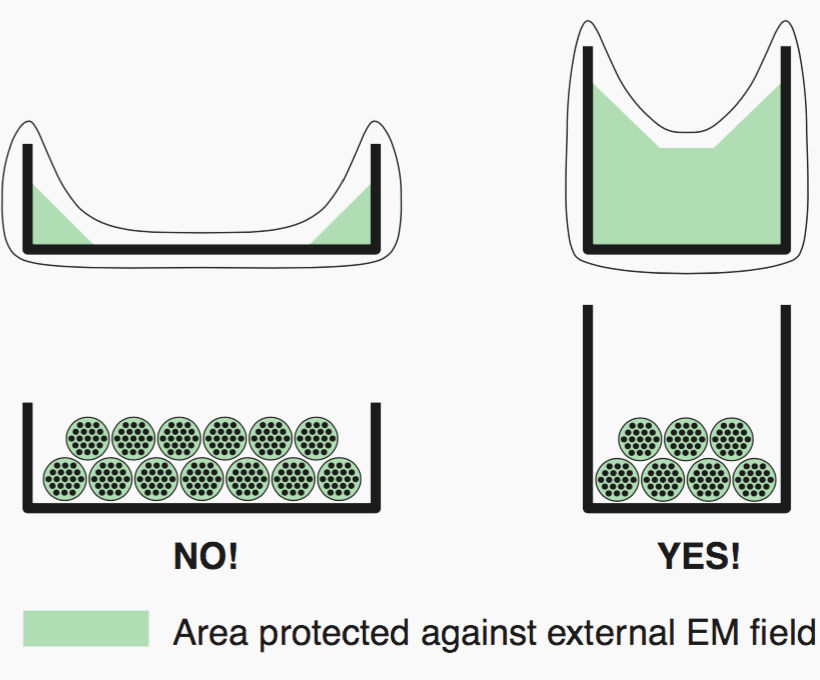
Different types of cables (power and low-level cables) should not be installed in the same bundle or in the same cableway. Cableways should never be filled to more than half capacity!!
Design recommendations
It is recommended to electromagnetically separate groups from one another, either using shielding or by installing the cables in different cableways. The quality of the shielding determines the distance between groups. If there is no shielding, sufficient distances must be maintained (see Figure 3).
The distance between power and control cables must be at least 5 times the radius of the larger power cable.
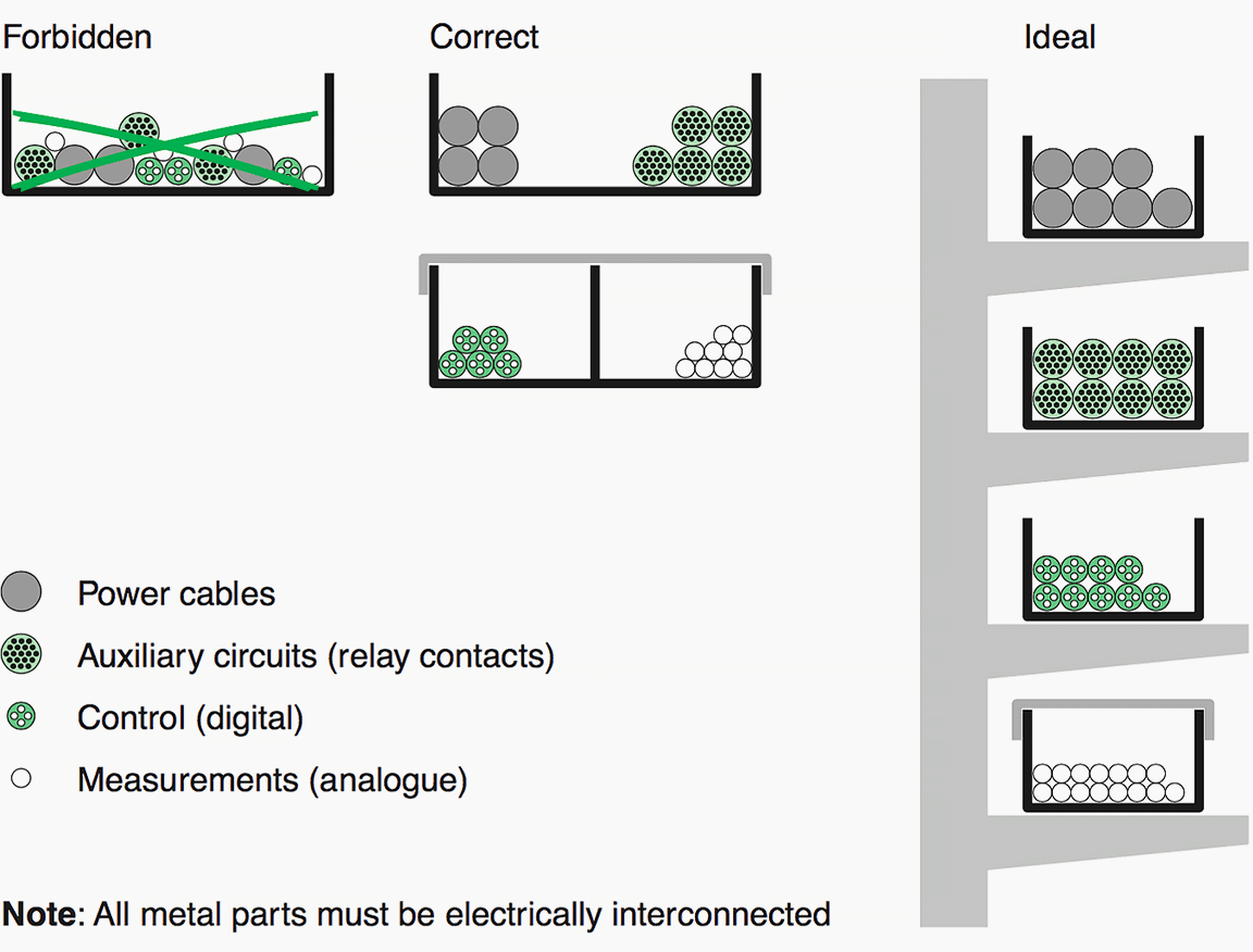
Metal building components can be used for EMC purposes. Steel beams (L, H, U or T shaped) often form an uninterrupted earthed structure with large transversal sections and surfaces with numerous intermediate earthing connections.
Cables should if possible be run along such beams. Inside corners are better than the outside surfaces (see Figure 4).
Both ends of metal cableways must always be connected to local earth network. For very long cableways, additional connections to the earthing system are recommended between connected devices.
Metal and non-metal cableways are available
Metal solutions offer better EMC characteristics. A cableway (cable trays, conduits, cable brackets, etc.) must offer a continuous, conducting metal structure from beginning to end.
An aluminium cableway has a lower DC resistance than a steel cableway of the same size, but the transfer impedance (Zt) of steel drops at a lower frequency, particularly when the steel has a high relative permeability μr.
Care must be taken when different types of metal are used because direct electrical connection is not authorised in certain cases to avoid corrosion. That could be a disadvantage in terms of EMC.
When devices connected to the wiring system using unshielded cables are not affected by low-frequency disturbances, the EMC of non-metal cableways can be improved by adding a parallel earthing conductor (PEC) inside the cableway. Both ends must be connected to the local earthing system. Connections should be made to a metal part with low impedance (e.g. a large metal panel of the device case).
The parallel earthing conductor (PEC) should be designed to handle high fault and common-mode currents.
Implementation of cableways
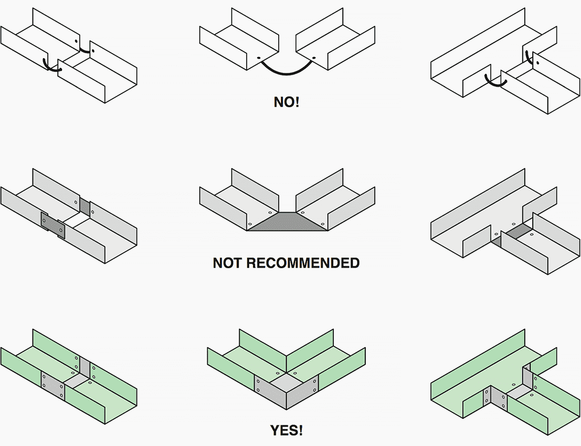
When a metal cableway is made up of a number of short sections, care is required to ensure continuity by correctly bonding the different parts. The parts should preferably be welded along all edges. Riveted, bolted or screwed connections are authorised as long as the contact surfaces conduct current (no paint or insulating coatings) and are protected against corrosion.
When a particular shape of cableway is selected, it should be used for the entire length. All interconnections must have a low impedance. A single wire connection between two parts of the cableway produces a high local impedance that cancels its EMC performance.
Starting at a few MHz, a ten-centimetre connection between two parts of the cableway reduces the attenuation factor by more than a factor of ten (see Figure 5).
Each time modifications or extensions are made, it is very important to make sure they are carried out according to EMC rules (e.g. never replace a metal cableway by a plastic version!!!).
Covers for metal cableways must meet the same requirements as those applying to the cableways themselves. A cover should have a large number of contacts along the entire length. If that is not possible, it must be connected to the cableway at least at the two ends using short connections (e.g. braided or meshed connections).
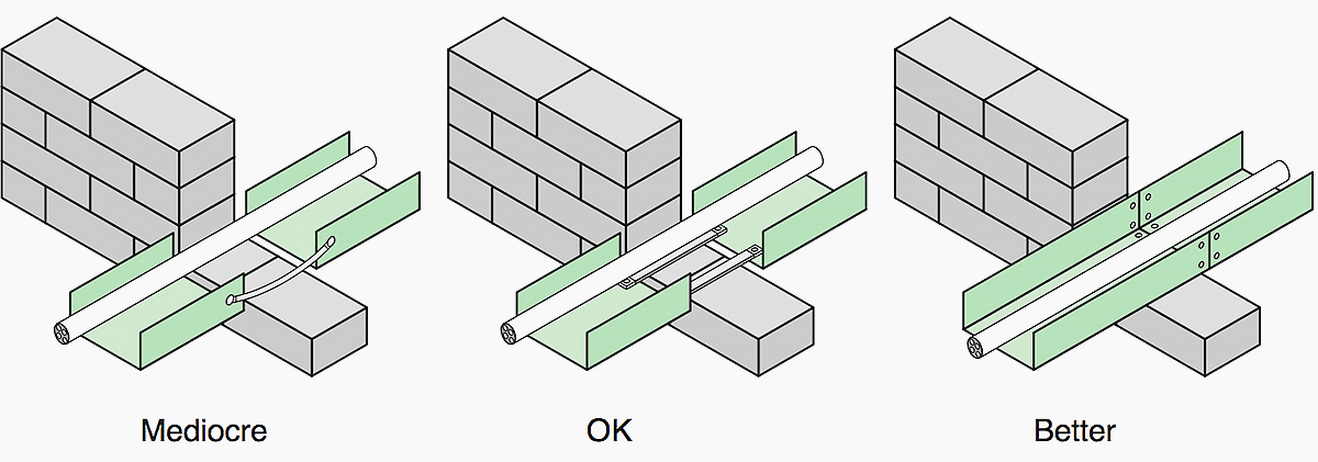
When cableways must be interrupted to pass through a wall (e.g. rewalls), low-impedance connections must be used between the two parts (see Figure 6).
Reference // Electrical Installation Guide 2016 by Schneider Electric


What are the recommendations when installing medium voltage cables from 2 different feeders on the same cable ladder?
electromagnetic interference
What’sz mean EMI ?
Thank you