
Estimated Study Time: 11 minutes
Capacitor banks and steps
Depending on the size of a compensation unit, it is assembled with capacitors of equal size (in bigger units) or of different size. A unit with a total reactive power of, for example, 300 kvar consists of six power capacitors, of 50 kvar each.
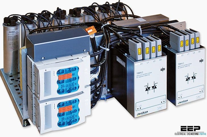 How to calculate number of steps & reactive power of the capacitor banks (photo credit: Janitza electronics)
Thus the number of capacitors is identical to the number of steps: six capacitors controlled by six steps.
However, compensation banks with unequal steps, for example 50 kvar and 25 kvar (see Figure 1), enable compensation in ‘fine-stepping’ mode. Smaller units up to 150 kvar approximately have combinations of different-sized capacitors for economic reasons.
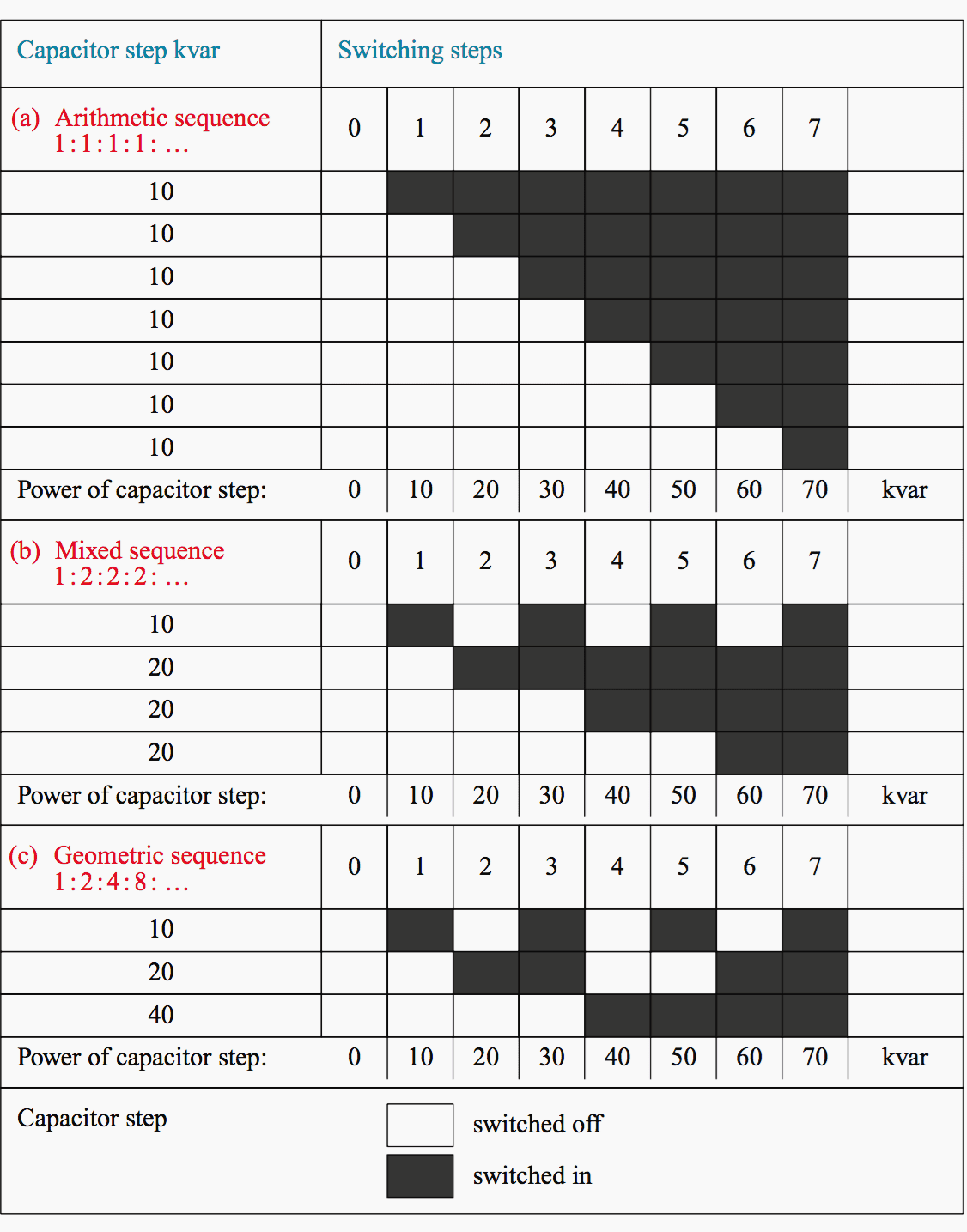
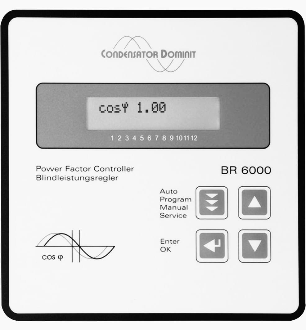
A compensation unit with a total of 110 kvar for instance is assembled with four capacitors of 10, 20 and 2 × 40 kvar (ratio 1:2:4:4) to enable control in 11 steps. Older power factor relays control with a fixed switching program, the so-called ‘geometrical switching sequence’ (see Figure 2).
Modern relays ‘pick out’ the correct capacitor size by referring to the actual demand of reactive power directly.
After determination of the total demand of reactive power to be compensated, it is then decided which types of compensation units (see this article) should be used. With regard to their locations, it should be kept in mind that the leads should be unburdened from reactive power at all time.
The power losses (kWh) along the leads increase in a squared manner with the apparent power (I2×R).
In smaller installations often one central-type compensation is quite sufficient. The power factor requested by the electricity supplier is to be kept on average within one billing period. Brief deviations from the power factor target must not be controlled quickly. Thus switching time delays per step of 30 to 40 s are quite sufficient.
It must be taken into consideration that shorter delays increase the number of switching operations, which often are counted up by modern power factor relays.
Another criterion for choosing compensation banks is the type of consumer. If there are only a few consumers with high rated power, a capacitor bank with rough stepping control is applicable. Installations with many middle-sized or small-sized consumers require compensation with fine-stepping control.
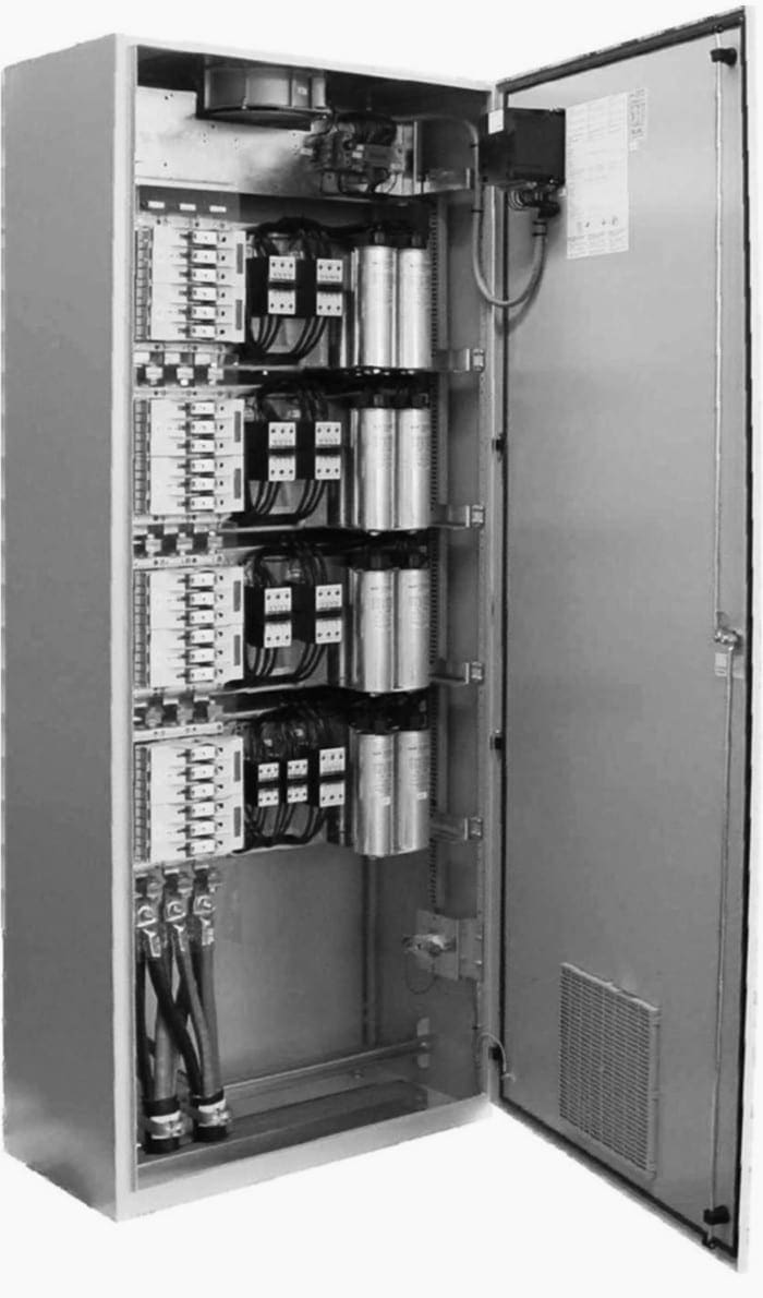
For this purpose more expensive compensation units with up to 12 or even 14 steps are available (Figure 3).
Where:
- (a) Control unit including power factor relay
- (b) Basic unit with steps 1–6
- (c) Extension unit with steps 7–12
- F1 – main fuses
- F2 – control fuses
- F3 – capacitor fuses
- K1–K12 – contactors
- P1 – power factor relay
- T1 – power transformer
- T2 – current transformer (to be installed at the distribution panel)
- X1 – control terminal
- X2 – plug connections between the modules
During the projecting period, a possible extension in future should be taken into consideration. This is to plan for enough space for the extension unit and furthermore to install a power factor relay with the additional control exits.
On completion of the installation, the extended compensation unit will be re-energized. First of all, the power factor relay checks all exits from the outset and recognizes the new capacitor steps (see Figure 4a and 4b).
Older power factor relays still working in many plants around the world follow a strict switching program, for example switching step 1 up to 6 or down from 6 to 1 or 0 (see Figure 2, arithmetic sequence).
Therefore modern power factor relays have changed to the so-called rotational or circular switching program as shown in Figure 5. This program distributes the operating hours equally to the capacitors.
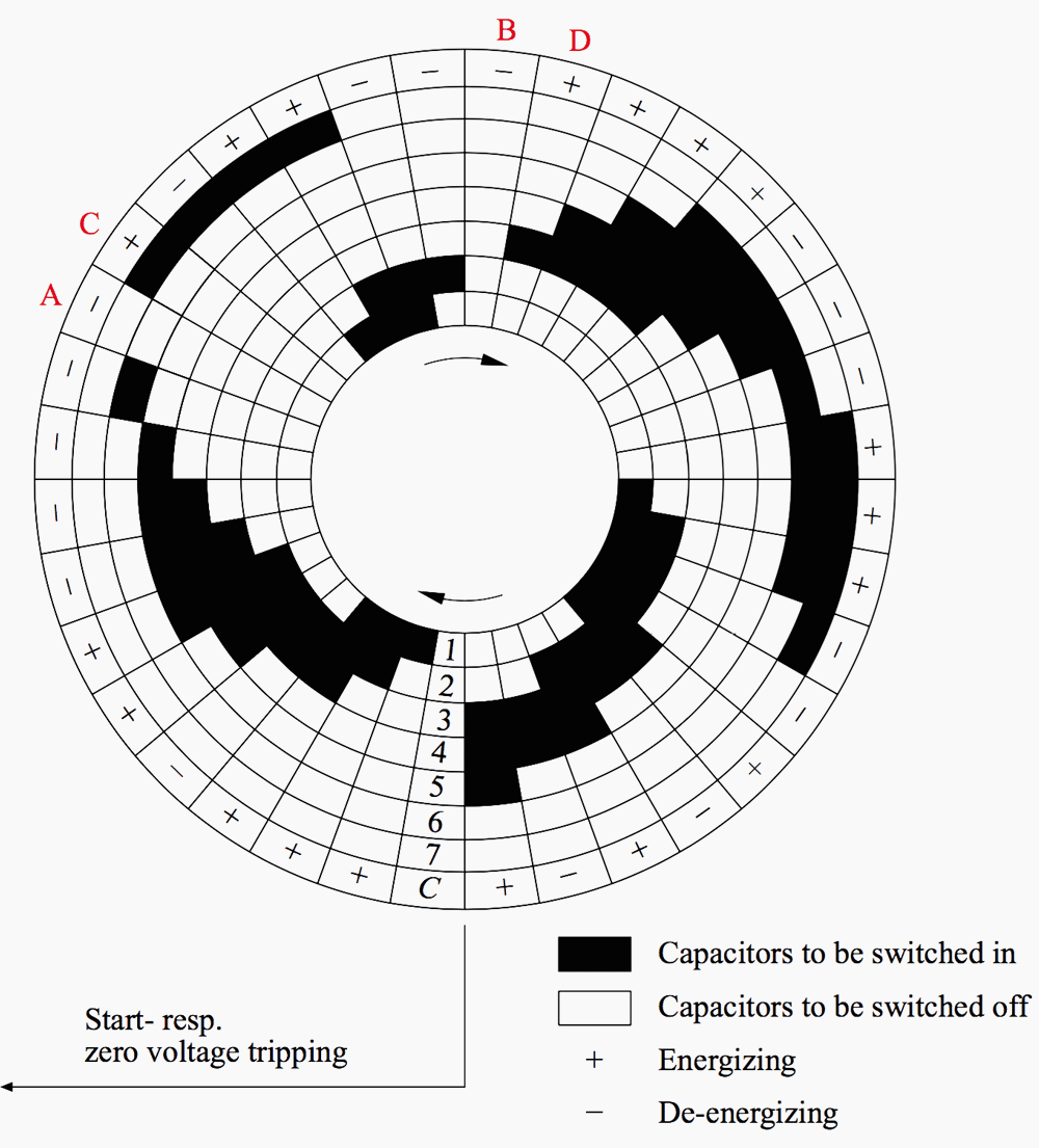
The capacitor energized for the longest time during the control procedure will be disconnected first and the capacitor which has been switched off the longest time will be connected next. Even for instance at finishing time on Friday (see sectors A & B), if all capacitors are switched off, on Monday morning then capacitor 7 or 3 will be energized first referring to sectors C and D accordingly, provided that there was no zero volt tripping in the meantime.
As mentioned above, smaller compensation units work with capacitors of different sizes, for example 10 kvar, 20 kvar and two capacitors of 40 kvar each. Due to the power ratio 1:2:4:4, the so-called geometric sequence (see Figure 2) is used many times.
The first step of 10 kvar symbolizes the stepping size of the compensation bank and has the highest number of switching operations during its life. It will be switched in and out four times up to the final step 7, strictly following the switching program.
This saves switching operations regarding the 10 and 20 kvar capacitor especially; they will be brought into the control procedure if the actual deviation of reactive power exceeds two-thirds (66%) of either 10 or 20 kvar only. This determines the so-called ‘C/k’ value – value that is calculated by the step size C divided by the ratio k of the current transformer.
Threshold Level C/k Value
Most compensation banks are controlled stepwise. For this purpose it is essential to ‘know’ when it is allowed to (de)activate a capacitor step by the power factor relay.
The so-called C/k value is calculated by the step size C divided by the ratio k of the current transformer.
It is clear that a capacitor with, for instance, 50 kvar may not be switched in if the power factor relay measures a deviation of just 10 kvar reactive power with regard to the preadjusted power factor target. If so, 40 kvar would ‘hang over’ to the other side of the line representing the power factor target (see Figure 6).
The relay would switch off due to the level of 10 kvar. This procedure, called ‘hunting’ (oscillating), would repeat steadily. This danger occurred in older power factor relays with manual C/k adjustment when it was preset wrongly, or too low. Two-thirds (66%) of a step size at least must exist as deviation to enter the control procedure. The percentage may vary between 65 and 85% with reference to realistic tolerances of the capacitor, current transformer and power factor relay itself.
- If the sensed apparent current vector lies within the bandwidth, any control of reactive power is to be stopped.
- If the vector exceeds the threshold level to the right, the power factor relay has to switch in capacitor steps.
- If the vector exceeds the threshold level to the left, capacitor steps have to be disconnected in order to bring the vector within the bandwidth again.
All power factor relays have to follow the mathematical description accordingly in order to avoid any ‘hunting’:
Where:
- C/k – necessary level of reactive current to enter control procedure (Ar = amperes reactive)
- Qc – capacitor step (kvar)
- U – delta voltage of the grid (kV)
- k – ratio of the current transformer
In modern microprocessor-controlled relays the correct C/k adjustment ensues automatically. They succumb to the minimum of sensibility of 1% as well; at lower values the relays are not able to ‘recognize’ capacitor steps. Therefore the C/k value and its meaning are very important to aid understanding.
In time, reactive power factor relays with manual C/k adjustment are destined to die out.
Reference // Reactive power compensation by Wolfgang Hofmann, Jurgen Schlabbach and Wolfgang Just (Purchase hardcopy from Amazon)
Related electrical guides & articles


Edvard Csanyi
Hi, I'm an electrical engineer, programmer and founder of EEP - Electrical Engineering Portal. I worked twelve years at Schneider Electric in the position of technical support for low- and medium-voltage projects and the design of busbar trunking systems.I'm highly specialized in the design of LV/MV switchgear and low-voltage, high-power busbar trunking (<6300A) in substations, commercial buildings and industry facilities. I'm also a professional in AutoCAD programming.
Profile: Edvard Csanyi

Hello.
Am a certified wireman and also freelance electrician
information of great value for those of us who are dedicated to the energy quality business
Thanks for sharing
Fantastic article for Power Quality experts, hats off 👏 to Mr.Edvard
Alexandria, Egypt 🇪🇬
It’s really fantastic and reminded again how to calculate the capacitor bank required for the total connected load.
Regards
It’s Realy useful.
I want to the calculation steps of PFI unit.
80% of the load is thyristor load, so how do I calculate the power factor?
My total load is 1000 kW.
Good file
It is extremely important and Excellent topic
Why in a small factory a cetral bank of delta connected capacitors in the schematic connected to the power unit you see two resistors connected at a common point of the Delta and then the other end each at a different phase.
Hi,
I work for Festo Didactic inc. who is a company of didactic material. We develop material equipment and produce a courseware for student on Power Factor Controller. I’m an engineer but not specialist in PFC. Is it possible for you to act as a consultant for us in this project ? I have some questions and you may be a guy who give me the good answer.
Regards,
It’s A very helpfull article
thanks for help me
You are more than certain Prof.i thought you had PHD. I will contact you once some things appear not clear. Thanks
Fantastic Article.