
Estimated Study Time: 7 minutes
Short-Circuit Effects
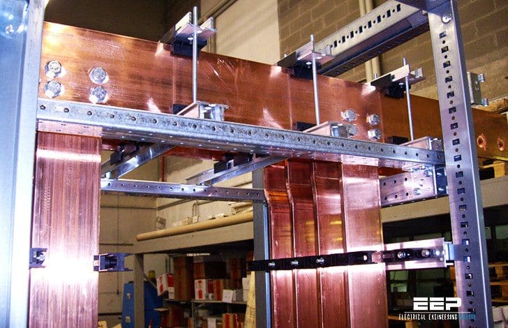
Like all electrical circuits, busbars need to be protected against the effects of short-circuit currents. The open construction of busbars increases the risk of faults, e.g. by the ingress of foreign bodies into air gaps, and the risk of consequent damage is high due to their high normal operating currents and the amount of energy available.
Very high currents lead to rapid and extreme overheating of the bars with consequent softening of the material and damage to the support structure. At the same time, the electromagnetic forces generated will distort the softened conductors which may break free from their supports.
Resonance effects may make the situation worse.
Heating Caused By Short-Circuit
The maximum potential short-circuit current depends on the source impedance of the supply and reduces along the length of the bar as the impedance increases. For the purpose of ensuring the safety and integrity of the bar, the short circuit current should be initially calculated close to the feed end of the bar, making no allowance for bar impedance, to establish the worst case.
When a fault occurs, the short-circuit current will be many times the normal operating current and will flow until the protective device operates.
Because the time duration is small – a few seconds at most – it is usual to assume adiabatic heating, in other words, that, over the time scale of interest, there is no significant cooling effect and that all the heat generated by the current flow is retained in the bar.
The amount of heat energy required to raise the temperature of a unit mass of material by one degree Centigrade is called the specific heat. For copper, at room temperature, the value is 385 Joule/kg/K.
Knowing the mass of the bar and the energy produced by the short circuit current, the temperature rise can be calculated:

where:
- Q is the amount of heat added to the bar (Joule)
- S is the specific heat of the bar material (J/kg/K)
- m is the mass of the bar (kg)
- tr is the temperature rise.
The amount of energy dissipated in the bar is:
![]()
where:
- P is the power dissipated in the bar (W)
- T is the time for which the power is dissipated (seconds).
Therefore,

where Δtr is the rate of temperature rise in degrees C per second. The power dissipated in the bar is given by:

where:
- R is the resistance of the bar (Ω)
- r is the resistivity of the bar material (Ωm) l is the length of the bar (m)
- A is the cross-sectional area of the bar (m2).
Substituting for W and M gives:

where:
- D is density (kg/m3).
Two of the physical constants, specific heat and resistivity, vary considerably with temperature so it is not obvious which values should be used. Resistivity increases with temperature (by a factor of 1.6 from 20°C to 300°C) so increasing the energy dissipated as the temperature increases, while specific heat falls by around 8% over the same range.
Using room temperature values, and adjusting to use convenient units, gives the initial rate of temperature rise as:

where:
- I is current in kA
- A is the cross-sectional area in mm2.
The worst case rate of rise at the feed end of the bar is approximately:

However, if the short circuit is at some distance from the feed end, the fault current magnitude will be lower due to the resistance of the bar and will reduce further as the bar temperature rises.
Practice Tips
In practice, what is important is that the final temperature of the bar remains lower than the limiting design temperature throughout the short circuit event. The limiting temperature for copper busbars is determined by the temperature resistance of the support materials but, in any case, should not exceed ~ 200°C. The maximum circuit breaker tripping time is 200/Δtr seconds.
Busbars that have been subject to short circuit should be allowed to cool and inspected before being returned to service to ensure that all joints remain tight and that the mountings are secure.
Note that, although the heating time – the duration of the fault – is quite short, the bar will remain at high temperature for a considerable length of time. Also, because of the very high thermal conductivity of copper, parts of the bar beyond the fault will also have become hot.
Reference // Guidance for Design and Installation – David Chapman & Professor Toby Norris
Related electrical guides & articles


Edvard Csanyi
Hi, I'm an electrical engineer, programmer and founder of EEP - Electrical Engineering Portal. I worked twelve years at Schneider Electric in the position of technical support for low- and medium-voltage projects and the design of busbar trunking systems.I'm highly specialized in the design of LV/MV switchgear and low-voltage, high-power busbar trunking (<6300A) in substations, commercial buildings and industry facilities. I'm also a professional in AutoCAD programming.
Profile: Edvard Csanyi

It begins very well and come to tr=PT/Sm. Suddenly after substitution time T got lost and no more appeared in formula.
Logically dissipated heat and final temperature (raise) highly depend on the time.
From practice tips: “The maximum circuit breaker tripping time is 200/Δtr seconds.” Actually tripping time probably shall be set to less than 200/Δtr seconds?
very valuable explanation for electrical engrs.,civil engrs and civil construction engrs and builders
inferences can be drawn for many activities.
very excellent article;however, from physics point of view, length of busbar at the point of fault must have an impact so L should be part of the calculation and can not be neglected. If this is true, how can we prove this?
Sometimes I read articles here. In this one I’ve looked on the math. Just for the reason of curiosity we could do the calculations a slightly different way. In the article you mentioned “Therefore it is assumed that the temperature rise of the bar is simply linear – this simplifies the calculation significantly and yields a conservative result (A similar simplification is made in determining cable behavior under fault conditions.)” This point actually leads us to the following solution:
Q = integral(I^2*R*dt, t=0..T). R = R_0*(1+alpa*temperature). It’s assumed that temperature = temperature_0+betta*temperature (linearity assumption). Then
Q = integral(I^2*R_0*(1+alpa*{temperature_0+betta*temperature})*dt, t=0..T). ==>
Q = I^2*R_0*(T+alpa*{temperature_0*T + 1/2 * T^2*betta}. The factor betta describes physical dimensions and Is.c. magnitude.
Regards.
I think that
1- L (busbar length ) is effected .
2- tr used for set of bimetal relay