
Estimated Study Time: 17 minutes
Calculation of currents & power
Currents and power analysis are key factors in any design or redesign of an installation they will enable the source(s) to be sized according to the purpose of the installation, the intended use of the circuits and the receivers to be supplied.
 Detailed calculation of currents and power according to the type of load
The current consumed Ia corresponds to the nominal current consumed by a receiver independently of the utilisation factor and the coincidence factor, but taking into account the aspects of efficiency (η factor), displacement factor or phase shift (cos φ) for motors or other inductive or capacitive loads.
Let’s break the calculation of the power into few parts, so we can easily follow:
- Purely resistive load
- Non-distorting load that is not purely resistive
- Calculation of the current
- Overloads on conductors according to the total harmonic distortion
- Distorting load that is not purely resistive
1. Purely resistive load
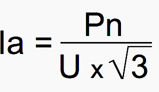
The current consumed Ia of a purely resistive load is calculated by simply applying the formulas. For single phase:

and for the three-phase:
Go back to currents and power calculations ↑
2. Non-distorting load that is not purely resistive
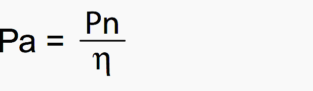
The nominal power (Pn) of a motor corresponds to the mechanical power available on its shaft. The actual power consumed (Pa) corresponds to the active power carried by the line.
This is dependent on the efficiency of the motor:
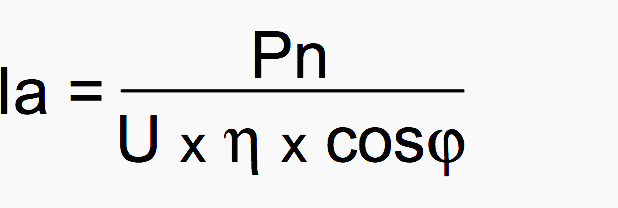
The current consumed (Ia) is given by the following formulae. For single-phase:
and for the three-phase:
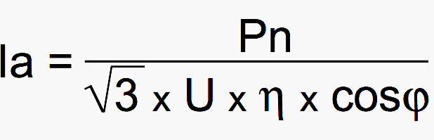
Where:
- Ia – rms current consumed (in A)
- Pn – nominal power (in W; this is the useful power)
- U – voltage between phases in three-phase, and between phase and neutral in single-phase (in V)
- η – efficiency
- cosφ – displacement factor
Go back to currents and power calculations ↑
3. Calculation of the current consumed by several receivers
The example described below shows that the current and power calculations must be carried out in accordance with precise mathematical rules in order to clearly distinguish the different components.
Example of asynchronous motors
A group of circuits consists of two three-phase asynchronous motors M1 and M2 connected to the same panel (mains supply: 400V AC – 50 hz). The nominal power of the motors are respectively: Pn1 = 22 kW and Pn2 = 37 kW.
Calculation of the power consumed:

The reactive power can in this case be calculated by determining the value of tanφ from cosφ. the relationship with the tangent is given by the formula:

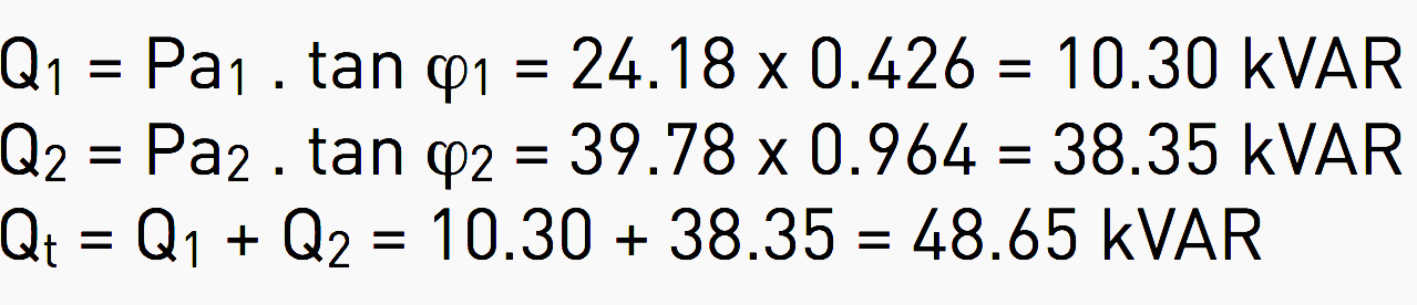
Calculation of the reactive power:
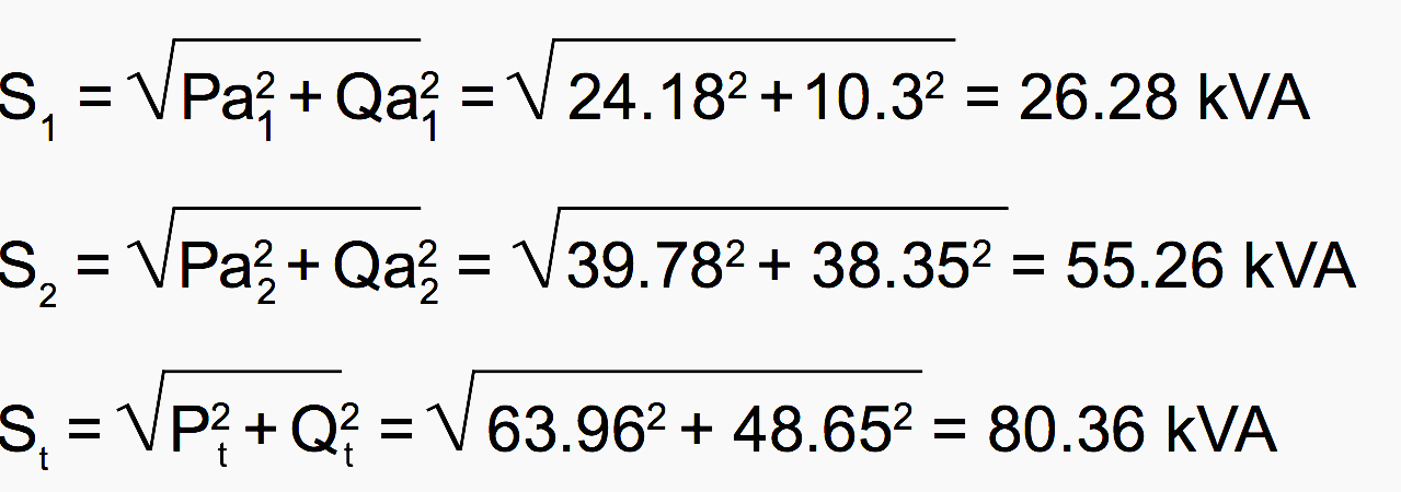
Calculation of the apparent power:
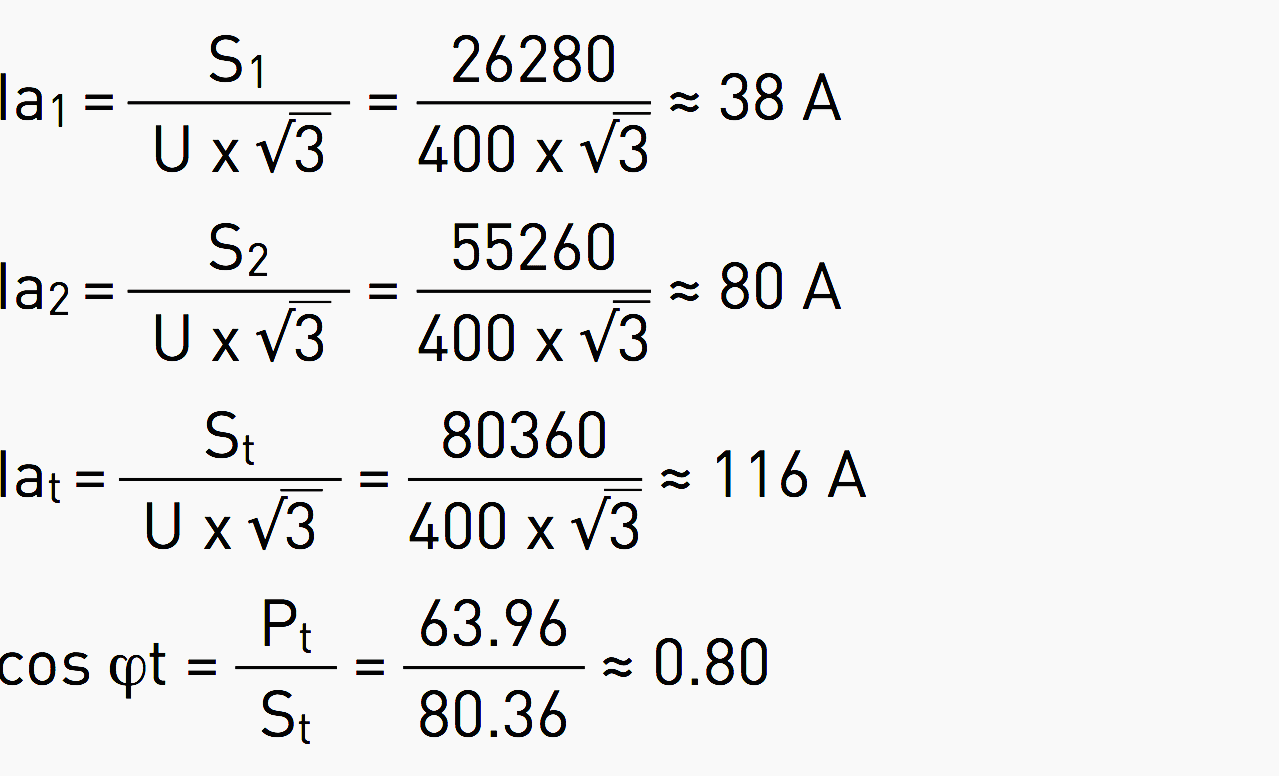
Calculation of the total current consumption for M1, M2, M1 + M2 and the corresponding power factor:
Go back to currents and power calculations ↑
Presentation of the results
All power analyses must show, as in the table below, at least for each group of:
- Active power circuits which corresponds (to the nearest efficiency) to the energy supplied,
- Reactive power so that the compensation devices (capacitors) can be sized,
- Apparent power so that the power of the source can be determined and
- Current consumed so that the trunking and protection devices can be calculated.
| M1 | M2 | M1 + M2 (Total t) | |
| Active power: P [kW] | Pa1 = 24.18 | Pa2 = 39.78 | Pt = 63.96 |
| Reactive power: Q [kVAR] | Q1 = 10.30 | Q2 = 38.35 | Qt = 48.65 |
| Apparent power: S [kVA] | S1 = 26.28 | S2 = 55.26 | St = 80.36 |
| Current consumed: Ia [A] | Ia1 = 38 | Ia2 = 80 | Iat = 116 |
| cosφ | 0.92 | 0.72 | 0.80 |
Go back to currents and power calculations ↑
4. Overloads on conductors according to the total harmonic distortion
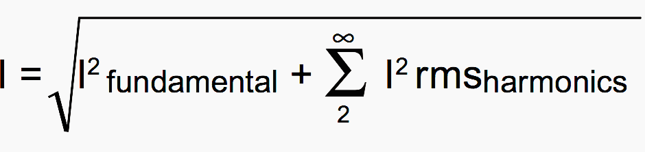
The current circulating in each phase is equal to the quadratic sum of the fundamental current (referred to as 1st harmonic order) and all the harmonic currents (of the following orders):
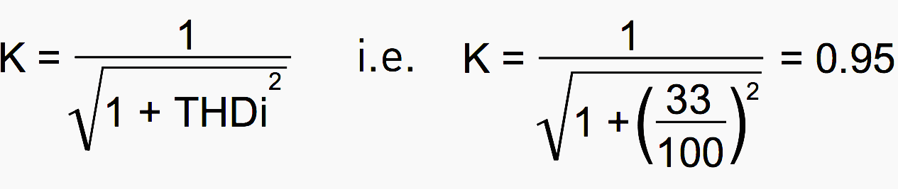
The THDi (Total Harmonic Distortion) expresses the ratio between the share of all the harmonic currents and the total current as a percentage.

I1 being the rms value of the fundamental and in In the rms value of the nth order harmonic. The principle is to apply a current reduction factor that can be calculated based on the THDi.
For a permissible THDi value of 33%, the current must thus in theory be reduced in each phase by a factor K:
If the factor is not applied, the current will then be increased by:
![]()
This remains acceptable and explains why the standard does not recommend any derating or oversizing of cross-sections up to 33% THDi.
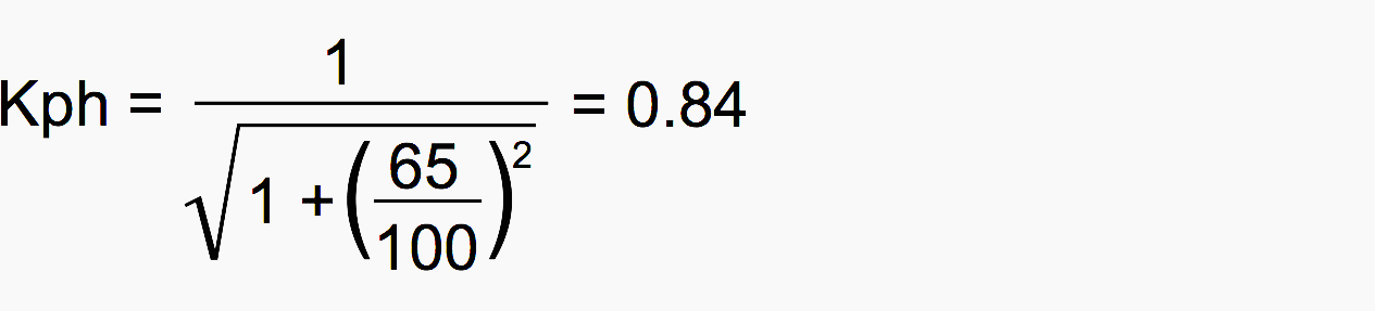
Reduction of the current or oversizing of multi-core cables may also be necessary for the phase conductors. It should be noted that the standard recommends a reduction factor of 0.84. which in fact corresponds to a pessimistic THDi of 65%.
Related to the neutral conductor, it is considered that if all the harmonics are 3rd order and its multiples, they will be added together and the current due to the harmonics in the neutral will then be IN = 3 × Iph, which can be expressed using an equivalent notation, THDn = 3 THDi.
But this current is never expressed directly because it involves a fairly complex mathematical calculation, the fourier transform, to ascertain its relative overall part (THDi: total harmonic distortion) or the value order by order: ih2, ih3, ih4, ih5,..ihn.
With no precise measurements, it is difficult to know exactly the current level that corresponds to each harmonic order. It is therefore preferable to simply increase the cross-section of the neutral conductor as a precaution, since it is known that the main 3rd order harmonics and their multiples are added together in the neutral. and to adapt the protection of this conductor.
Standard IEC 60364 indicates the increasing factors to be applied to the cross-section of the neutral conductor according the percentage of 3rd order harmonics.
In principle, the neutral must be the same cross-section as the phase conductor in all single-phase circuits. In three-phase circuits with a cross-section greater than 16 mm2 [25 mm2 aluminium]. The cross-section of the neutral can be reduced to cross-section/2.
However this reduction is not permitted if:
- The loads are not virtually balanced
- The total 3rd order harmonic currents are greater than 15%
If this total is greater than 33%, the cross-section of the active conductors of multi-core cables is chosen by increasing the current In by a fixed multiplication factor of 1.65. For single-core cables, only the cross-section of the neutral is increased.
The current reduction factor KN or rather its inverse which will be used to oversize the neutral conductor will then be:

With a total 3rd order harmonic distortion of 65%, the current of the phase conductors must be increased by 119% and that in the neutral conductor by 163%. If the THDi were to reach 100%, 1/KN would theoretically reach 2.12. This value would be impossible to reach as it would mean that the harmonic had totally replaced the fundamental.
The theoretical overcurrent limit for the neutral in relation to the phases is:
![]()
Go back to currents and power calculations ↑
Example of following the standards for defining a protection device with neutral overloaded by harmonics
For a 3P+N circuit, intended for 170 A, with TNS system, with total 3rd order harmonic distortion of more than 33%. When sizing the phase cables, the reduction factor of 0.84 (loaded neutral, see above) must be included.
This requires a minimum cross-section of 70 mm2 per phase. The neutral conductor must be sized to withstand a current of 1.45 × 170 A = 247 A, i.e. a cross-section of 95 mm2.
A circuit breaker must therefore be chosen that is capable of withstanding the current that may cross the neutral:
In device ≥ IB neutral ⇒ In = 250 A
But the device must be set according to the current that may flow in the phases:
Ir ≥ IB phases ⇒ Ir ≥ 170 A (and < 206 A, limit of the cable)
Go back to currents and power calculations ↑
5. Distorting load that is not purely resistive
The current consumed (Ia) is given by the following formulae:

where:
- Ia – rms current consumed (in A)
- Pn – nominal power (in W; this is the useful power)
- U – voltage between phases in three-phase, and between phase and neutral in single-phase (in V)
- η – efficiency
- PF – power factor
Go back to currents and power calculations ↑
Example of a fluorescent luminaire and electronic ballast
The nominal active power consumed by the luminaire is 9 W, and the measured apparent power is 16 VA. The measured displacement factor is cosφ = 0.845 and the power factor PF = 0.56.
The measured current consumed Ia is 0.07 A. As cosφ and the power factor are different, it is not possible to calculate the value of the tanφ or that of the reactive power Q (VAR) for the receiver in question.
The powers relative to this linear and sinusoidal part of the load can be calculated as follows
- S = 230 × 0.045 = 10.3 VA
- P = S × cosφ = 10.3 × 0.85 = 8.7 W
- Q = 5.5 VAR which is confirmed by the calculation of the power triangles Q2 = P2 – S2 or by the tanφ:
Q = P × tanφ = 8.7 × 0.63 = 5.5 VAR
It can also be seen that the sinusoidal active power of the device 8.7 W is very similar to the measured total active power 9 W. It can therefore be deduced that a large part of power S (16 – 10.3 = 5.7 VA) is consumed without producing any active power. The fluorescent luminaire and electronic ballast in the example consumes unproductive power in the form of harmonic currents.
The total harmonic distortion is easy to calculate and represents expressed as a rate.
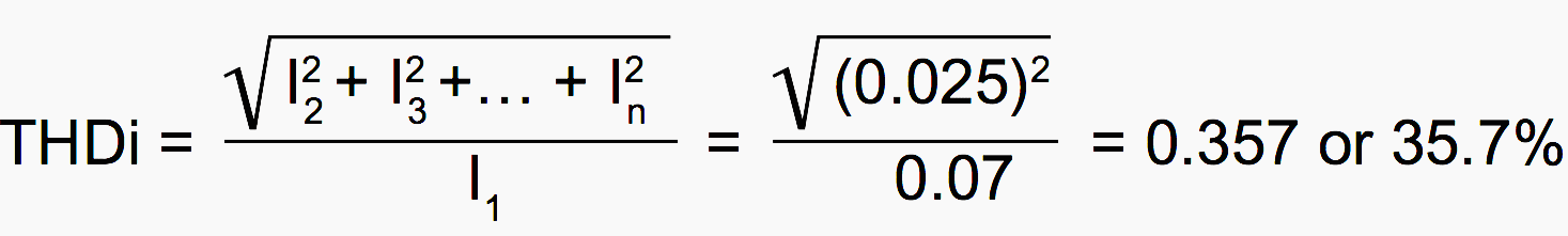
The spectral decomposition of the signal carried out on this luminaire shows that the main harmonic is 3rd order (34 mA) but that all the following odd-order harmonics are present and decaying. The main purpose of the above example is to demonstrate that active power information (in W) only for a non-linear receiver is very inadequate.
In the example given, it can be seen that an active power of approximately 9 W corresponds to a consumed power of 16 VA.
Many modern devices (light bulbs, computer equipment, domestic appliances and electronic equipment) have this particular feature of consuming non-linear currents. For domestic use, where only the power in W is billed (sic), the power savings shown for these products is attractive. In practice, the currents consumed are higher than it seems and the energy distributor is supplying wasted energy.
In large commercial or industrial installations the situation is different. A poor power factor results in consumption of reactive power that is billed. Compensation of non-linear loads thus becomes meaningful and useful here, but also at the design stage when it prevents oversizing of the energy sources, which it must be remembered supply VA (volt-amperes) and not W (watts).
Important: Unlike linear loads (page 29), for non-linear loads the active powers (in W) can be added together algebraically, the apparent powers must only be added together geometrically, and likewise the currents which must be the same order.
The reactive powers Q must not be added together except to as certain the relative part of the power associated with the sinusoidal fundamental signal and the part connected with the harmonic signals.
Go back to currents and power calculations ↑
Reference // Power balance and choice of power supply solutions by Legrand
Related electrical guides & articles


Edvard Csanyi
Hi, I'm an electrical engineer, programmer and founder of EEP - Electrical Engineering Portal. I worked twelve years at Schneider Electric in the position of technical support for low- and medium-voltage projects and the design of busbar trunking systems.I'm highly specialized in the design of LV/MV switchgear and low-voltage, high-power busbar trunking (<6300A) in substations, commercial buildings and industry facilities. I'm also a professional in AutoCAD programming.
Profile: Edvard Csanyi

I1 is fundamental current but you used Irms for calculation THDi. There is a distortion power factor = PF/cosф = 0.56/0.846 = 0.662 = I1/Irms. Thus I1 = 0.07 x 0.662= 0.046 A (first harmonic current). There is a formula for distortion power factor = 1/sqroot(1+sq(THDi)) and from this formula THDi = 1.13= 113% Where is a mistake???
Finally you made the mistake in calculation of a sum of higher harmonic currents and this is not 0.025 A, but must be 0.0526 A = sqroot(0.07sq – 0.046sq). And THDf = 0.0526/0.046 =113% and THDrms = 0.0526/0.07 = 75%
Dear Sir,
Please advise my below point related to Harmonics.
Let suppose we are installing 100A Harmonic filter on 17% THDi and 608A load. After installation Harmonic filter let suppose the THDi will be achieved at 2% to 3%.
Please advise after this installation will it improve(less) the 608A load also or not? If yes, how much?
Thank you so much,
I follow your group, it’s very useful. you merit a great gift
Best regards
How to estimate and what deviation factors to apply for the electrical load of a high rise 40 floors office and residential apartments building .
Wgat deviation should be used for a.Each apartment or office on the electrical and hvac loads b. For the total building required load based on the number of offices and aoartments c.The building commons load and deviation.
Thank u for the information you are providing it helps a lot
Good job
Hey,
A very good website
i don’know how to thank y
best regards,
Edward, really you are doing a great service to the electrical engineering Fraternity. Shall these articles be published in other forums so as to disseminate the information to number of Electrical Engineers? Pl. reply to my mail. Earlier also I had asked the same questions on many times but you didn’t reply. So hope this time you will relay positively.
Thanks,
ULHAS VAJRE