
Estimated Study Time: 19 minutes
Introduction to calculations
Distribution substations with an installed power of 2×1600 kVA are a typical example of electrical power supply facilities which can be often seen all around Europe and wider. By “calculation” of such a substation, it is assumed that values of all relevant physical quantities shall be determined, and all major equipment inside the substation shall be specified according to these values.
 How to make calculation for a distribution substation 10/0.4 kV, 2x1600 kVA
Within this article, an example of this type of calculation for electrical equipment will be given.
A basic guide for calculations and dimensioning will be adequate IEC standards and practical engineering experience. Of course, besides electrical, there will be also civil and HVAC (Heating Ventilation and Air Conditioning) requirements for substation which need to be fulfilled, but they are out of the scope of this article.
1. Substation example
When we say “2×1600 kVA” that means two power transformers, each of them with rated power of 1600 kVA, will be installed inside substation.
Strictly speaking, but not necessary, 2×1600 kVA designation assumes a substation capable to cover a peak power demand of 2×1600=3200 kVA. That further implies a parallel operation of transformers, i.e. both transformers will carry the load at the same time.
On the other hand, when we want to emphasize that one transformer will be a working unit, while the other serves as a spare, a designation (1600+1600) kVA may be used. The latter means that the substation will be designed for a peak power demand of 1600 kVA.
This example will be based on 3200 kVA peak power demand requirement. Besides that, other major input data necessary for calculation and design are:
- Medium voltage rated value
- Low voltage rated value
- Medium voltage network short circuit power (or short circuit current)
- Number of medium voltage power supply cables
- Type of earthing arrangement
- Maximum ambient temperature
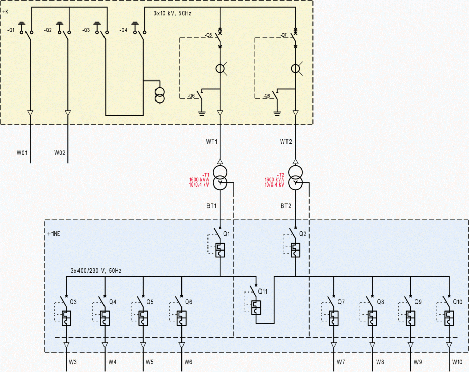
Single line diagram of distribution substation is given in Figure 1. Substation is supplied from 10 kV distribution network via two cables (typical solution for so called ring type of supply).
Medium voltage switchgear (design tag +K) supplies power transformers (design tag -T1 and -T2) with voltage transformation ratio of 10/0.4 kV/kV. Power is further distributed to consumers on 0.4 kV voltage level via busbar system (design tag BT1 and BT2) and main low voltage distribution switchboard (design tag +1NE).
The number and rating of outgoings, i.e. circuit breakers, inside +1NE switchboard is determined by predicted or actual number and consumption of consumers supplied from this substation.
Miodrag Kokotovic
Graduated from Faculty of Electrical Engineering, within University of Belgrade, in the field of electrical power systems. Expert in electrical part of tender preparation, design, procurement, construction and commissioning of treatment plants and pumping stations, electrical power quality and energy management.Profile: Miodrag Kokotovic
