
Estimated Study Time: 6 minutes
Example
– Array Size: 10, 12-volt, 51-watt modules; Isc= 3.25 amps, Voc= 20.7 volts
– Batteries: 800 amp-hours at 12 volts
– Loads: 5 amps DC and 500-watt inverterwith 90% efficiency.
Description
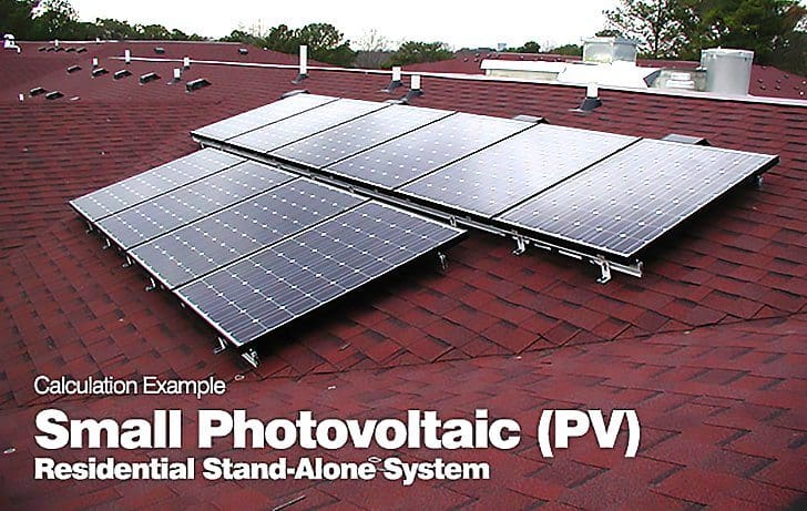
The PV modules are mounted on the roof. Single-conductor cables are used to connect the modules to a roof-mounted junction box. Potential reverse fault currents indicate that a PV combiner be used with a series fuse for each PV module.
UF two-conductor sheathed cable is used from the roof to the control center.
Physical protection (wood barriers or conduit) for the UF cable is used where required. The control center, diagrammed in Figure 1, contains disconnect and overcurrent devices for the PV array, the batteries, the inverter, and the charge-controller.

Calculations
– The moduleshort-circuit current is 3.25 amps.
– CONTINUOUS CURRENT: 1.25 x 3.25 = 4.06 amps
– 80% OPERATION: 1.25 x 4.06 = 5.08 amps per module
The maximum estimated moduleoperating temperature is 68°C.
From NECTable 310.17:
- The derating factor for USE-2 cable is 0.58 at 61-70°C.
- Cable 14 AWG has an ampacity at 68°C of 20.3 amps (0.58 x 35) (max fuse is 15 amps).
- Cable 12 AWG has an ampacity at 68°C of 23.2 amps (0.58 x 40) (max fuse is 20 amps).
- Cable 10 AWG has an ampacity at 68°C of 31.9 amps (0.58 x 55) (max fuse is 30 amps).
- Cable 8 AWG has an ampacityat 68°C of 46.4 amps (0.58 x 80).
The array is divided into two five-module sub-arrays.
The modules in each sub-array are wired from module junction box to the PV combiner for that sub-array and then to the array junction box. Cable size 10 AWG USE-2 is selected for this wiring, because it has an ampacityof 31.9 amps under these conditions, and the requirement for each sub-array is 5 x 4.06 = 20.3 amps.
Evaluated with 75°C insulation, a 10 AWG cable has an ampacity of 35 amps at 30°C, which is greater than the actual requirement of 20.3 amps (5 x 4.06).
In the array junction box on the roof, two 30-amp fuse sin pullout holders are used to provide overcurrent protection for the 10 AWG conductors. These fuses meet the requirement of 25.4 amps (125% of 20.3) and have a rating less than the derated cable ampacity.
Appropriately derated cables must be used when connecting to fusesthat are rated for use only with 75°C conductors. A 60-amp circuit breaker in the control box serves as the PV disconnect switch and overcurrent protectionfor the UF cable.
The minimum rating would be 10 x 3.25 x 1.56 = 51 amps.
The NEC allows the next larger size; in this case, 60 amps, which will protect the 70 amp rated cable. Two single-pole, pullout fuse holders are used for the battery disconnect. The charge circuit fuse is a 60-amp RK-5 type.
The inverter has a continuous rating of 500 watts at the lowest operating voltage of 10.75 volts and an efficiency of 90% at this power level. The continuous current calculation for the input circuit is 64.6 amps ((500 / 10.75 / 0.90) x 1.25).
The cables from the battery to the control center must meet the inverter requirements of 64.6 amps plus the DC load requirements of 6.25 amps (1.25 x 5).
A 4 AWG THHN has an ampacityof 85 amps when placed in conduit and evaluated with 75°C insulation. This exceeds the requirements of 71 amps (64.6 + 6.25). This cable can be used in the custom power center and be run from the batteries to the inverter.
The discharge-circuit fuse must be rated at least 71 amps. An 80-amp fuse should be used, which is less than the cable ampacity.
The grounding electrode conductor is 4 AWG and is sized to match the largest conductor in the system, which is the array-to-controlcenter wiring. This size would be appropriate for a concrete-encased grounding electrode. Equipment-grounding conductors for the array and the charge circuit can be 10 AWG based on the 60-amp overcurrent devices.
The equipment ground for the inverter mustbe an 8 AWG conductor based on the 80-amp overcurrent device. All components should have at least a DC voltage rating of 1.25 x 20.7 = 26 volts.
Reference: Photovoltaic Power Systems And the 2005 National Electrical Code – John Wiles Southwest Technology Development Institute New Mexico State University
Related electrical guides & articles


Edvard Csanyi
Hi, I'm an electrical engineer, programmer and founder of EEP - Electrical Engineering Portal. I worked twelve years at Schneider Electric in the position of technical support for low- and medium-voltage projects and the design of busbar trunking systems.I'm highly specialized in the design of LV/MV switchgear and low-voltage, high-power busbar trunking (<6300A) in substations, commercial buildings and industry facilities. I'm also a professional in AutoCAD programming.
Profile: Edvard Csanyi

Is the lowest operating voltage in the example given or need to be calculated? Many Thanks
Can i know how the lowest operating voltage calculated or is it given based on the specification of the inverter? many thanks
I have one doubt.
I am working solar plant. In my site SCB(String combiner box) fuse rating used 32amps.I can’t understand why this rating of fuse used in this SCB.
In my site PV module
Rated current-9.2A
Short circuit current-9.57A
Rated voltage-39.7v
Open circuit voltage-48.2v
Watts-365w
Please clarify to me why 32A fuse is used in scb .
Hi I’m Firdaus also working solar field, but base on standard that we used should be Itrip (tripping current of string fuse) is between 1.5 to 2.0 Isc_stc_mod ( short circuit current of module STC). So base on number you give the fuse is over size and by the way most of panel supplier already give the prefer fuse value that we should select for their panel.
A higher voltage is indicated, there is equipment (inverters, controllers) for 48 V or 56 V. Here is a video for design a standalone sistem:
https://www.youtube.com/watch?v=shHjh9QUB9g
Thanks, can I have solar installation book and electrical software and estimation software
Here is link for download document
https://www.dropbox.com/s/m3lzjfym4wx40a5/solar%20sistem.pdf?dl=0
Thanks Advard. Question why are the batteries -ve grounded. They can remain ungrounded, I believe it would be acceptable.
The rules for grounding electrical systems have evolved over time. Boat builders, installers, and electricians continue to recognize hazards and increase safety measures. Battery chargers were originally treated like any other small appliance, first without having any safety ground as was common through the 1950’s, and then by adding a safety ground to reduce shock hazards during faults.
It was found that faults in the DC wiring or the DC side of chargers could generate fires because high current could flow back from the batteries, so a fuse was added between inverters or chargers and the battery system. As the capacity of chargers increased, and with the introduction of inverters, these DC fuses became quite large. It was then determined that a fire hazard exists when a DC fault in a charger or inverter can pass DC current into the AC safety ground wire. The AC safety ground was not sized for the high DC currents, so a high capacity DC grounding wire is now required by standards A-20 and A-25.
PV is very essential in these days.Please send me the procedures and materials in installation of PV.
thanks for you , but i want video for complete instalation
Here is video : https://www.youtube.com/watch?v=shHjh9QUB9g
Some comments on the design:
1. Your PV module grounding is shown as connecting module-to-module and depending on modules in the chain to provide a ground path for other modules. This is not good practice. Generally an outdoor rated lay-in lug is used on each PV module and a single grounding conductor is run across all the modules in a panel. Loss of connection to one modules does not then cause loss of grounding on the other modules.
2. Generally, 12-volt PV modules can be placed in parallel without individual series diodes because the available voltage will not backfeed into a module. This is usually covered in the UL approved installation instructions for the specific PV module.
Hey Advard, just want to notice, on the system diagram there is no way to use the stored energy in the batterys. Usually the charge controler also had an exit for a DC loads.