
Estimated Study Time: 6 minutes
The basics of shaded-pole motors
First, let’s say few words about shaded-pole motors, and then dive into calculation procedure. A shaded pole motor is the simplest form of a single phase motor and is very low in cost.
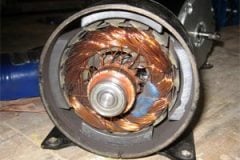
 Calculation of shaded-pole motor losses and efficiency at full load in 6 steps (photo credit: grayfurnaceman via Youtube)
It develops a rotating field by delaying the build up of magnetic flux through part of the pole structure. The shaded portion of the pole is isolated from the rest of the pole by a copper conductor that forms a single turn around it.
The magnetic flux in the unshaded portion increases with the current through its winding. Magnetic flux increases in the shaded portion.
However, it is delayed by the current induced in the copper field.
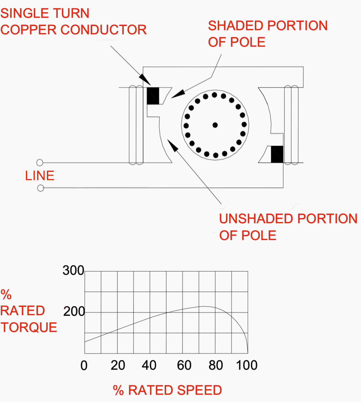
The magnetic field sweeps across the pole face from the unshaded portion to the shaded portion, developing a torque in the squirrel cage.
To maximize torque, the rotor is made with relatively high resistance.
Calculation Procedure
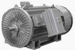
A four-pole shaded-pole motor (Figure 2) has the following data associated with it:
- Nominal voltage 120 V,
- Full-load delivered power of 2.5 mhp (millihorsepower),
- Frequency 60 Hz,
- 350-mA full-load curent,
- 12-W full-load power input,
- 1525 r/min full-load speed,
- 1760 r/min no-load speed,
- 6.6 W no-load power input,
- 235 mA no-load current, and
- Stator resistance measured with DC of 30.

Calculate the losses and efficiency at full load.
Step #1 – Calculate the Rotational Losses
From the no-load conditions, consider that the rotational losses of friction and windage are equal to the power input less the stator-copper loss. The stator resistance, measured with dc, was found to be 30 Ω.
Assume a value of 15 percent for this problem. The rotational losses Pfw equal:
Pfw = PNL – INL2(Rdc) = 6.6 W – (235 × 10-3 A)2(30 Ω)(1.15) = 6.6 W – 1.905 W = 4.69 W
(Rdc is dc-to-ac resistance-correction factor)
Step #2 – Calculate Stator-Copper Loss at Full Load
At full load the stator-copper loss Pscu is:
Pscu = IFL2(Rdc)(350 ×10-3 A)2(30 Ω)(1.15) = 4.23 W
Step #3 – Calculate the Slip
The synchronous speed for a four-pole machine is obtained from the relation n = 120 f/p, where f frequency in Hz and p the number of poles.
Thus, n = (120)(60)/4 = 1800 r/min.
Step #4 – Calculate Rotor-Copper Loss at Full Load
In induction machines, the rotor-copper loss is equal to the power transferred across the air gap multiplied by the slip. The power transferred across the air gap equals the input power minus the stator-copper loss. Thus, at full load:
Prcu = (12 W – 4.23 W) (0.153) = 1.2 W
Step #5 – Summarize the Full-Load Losses
| Stator-copper loss | 4.23 W |
| Rotor-copper loss | 1.2 W |
| Friction and windage loss | 4.69 W |
| Total losses | 10.12 W |
Step #6 – Calculate the Efficiency
The motor delivers 2.5 mhp. The input is 12 W or (12 W)(1 hp/746 W) = 16.1 mhp.
Therefore, the efficiency is:
η = (output)(100 percent) / input = (2.5 mhp)(100 percent) / 16.1 mhp = 15.5 percent
Alternatively, the developed mechanical power is equal to the power transferred across the air gap multiplied by:
(1 – s), or (12 W – 4.23 W)(1 – 0.153) = 6.58 W.
From this must be subtracted the friction and windage losses:
6.58 – W 4.69 W = 1.89 W, or (1.89 W)(1 hp/746 W) = 2 .53 mhp.
η = (input – losses)(100 percent) / input = (12 W – 10.12 W)(100 percent)/12 W
η = 15.7 percent.
References:
- Electric Motors – Energy Efficiency Reference Guide by CEA Technologies Inc.
- Handbook Of Electric Power Calculations by H. Wayne Beaty
Related electrical guides & articles


Edvard Csanyi
Hi, I'm an electrical engineer, programmer and founder of EEP - Electrical Engineering Portal. I worked twelve years at Schneider Electric in the position of technical support for low- and medium-voltage projects and the design of busbar trunking systems.I'm highly specialized in the design of LV/MV switchgear and low-voltage, high-power busbar trunking (<6300A) in substations, commercial buildings and industry facilities. I'm also a professional in AutoCAD programming.
Profile: Edvard Csanyi

in induction motor FLUKE 438-II claim to measure efficiency by just hooking meter on i/p side of motor and calculate efficiency without knowing no load losses and resistance of motor winding, how is possible, can anybody know any formula.
If you accurately measure the current of the motor with it’s normal load to find the
impedance. calculate the capacitance and parallel it with the motor. Non polarized 159V AC
caps work very well. My squirrel cage motor was near 250 ohms which was calculated
at 12.5uF. The current dropped from 500 ma to 320 ma. A parallel resonant circuit.
The motor is on it’s 4th year in a wood stove. I used 2 27 uf caps in series/ Do not use
back to back electrolytics, Mylar or polypropylene.
Thanks a lot to the help to understand the reasons of the so little efficiency of these motors.
Thanks a lot for these nice notes
Thanks for sharing this notes