
Reactive power
First, let’s say some words about basics of the reactive power in system. Reactive current arises in every electrical system. Not only large loads, but smaller loads as well require reactive power. Generators and motors produce reactive power, which causes unnecessary burdens to and power losses in the lines.
 4 example calculations of compensation for reactive power (photo credit: mavinelectric.files.wordpress.com)
Figure 1 shows the block diagram for the network loading.

Reactive power is necessary to generate magnetic fields, e.g. in motors, transformers and generators. This power oscillates between the source and the load and represents an additional loading.
Now, let’s take few examples to calculate the following:
- Determination of Capacitive Power
- Capacitive Power With k Factor
- Determination of Cable Cross-Section
- Calculation of the c/k Value
Example 1 – Determination of Capacitive Power
A load has an effective power of P = 50 kW at 400 V and the power factor is to be compensated from cosφ = 0.75 to cosφ = 0.95. Determine the required capacitive power. The power and current before compensation are:

The power and current after compensation are:

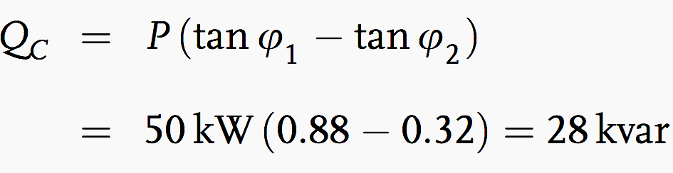
The required capacitive power is:
Example 2 – Capacitive Power With k Factor
The capacitive power can be determined with the factor k for a given effective power. The k factor is read from a table 1 – Multipliers to determine capacitor kilovars required for power factor correction (see below) and multiplied by the effective power. The result is the required capacitive power.
For an increase in the power factor from cosφ = 0.75 to cosφ = 0.95, from the table 1 we find a factor k = 0.55:
![]()
Example 3 – Determination of Cable Cross-Section
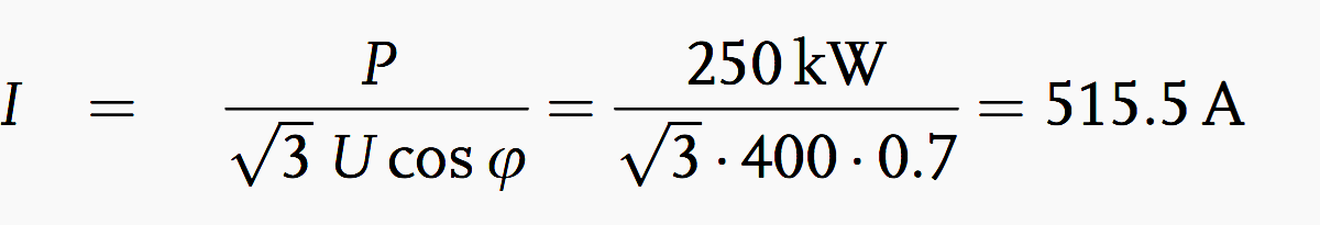
A three-phase power of 250 kW, with Un = 400 V, at 50 Hz is to be transmitted over a cable 80 m in length. The voltage drop must not exceed 4% =16 V. The power factor is to be increased from cosφ = 0.7 to cosφ = 0.95. What is the required cable cross-section?
![]()
The current consumption before compensation is:
The current consumption after compensation is:

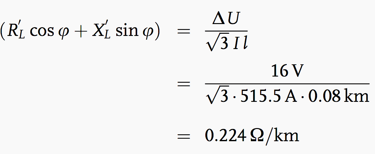
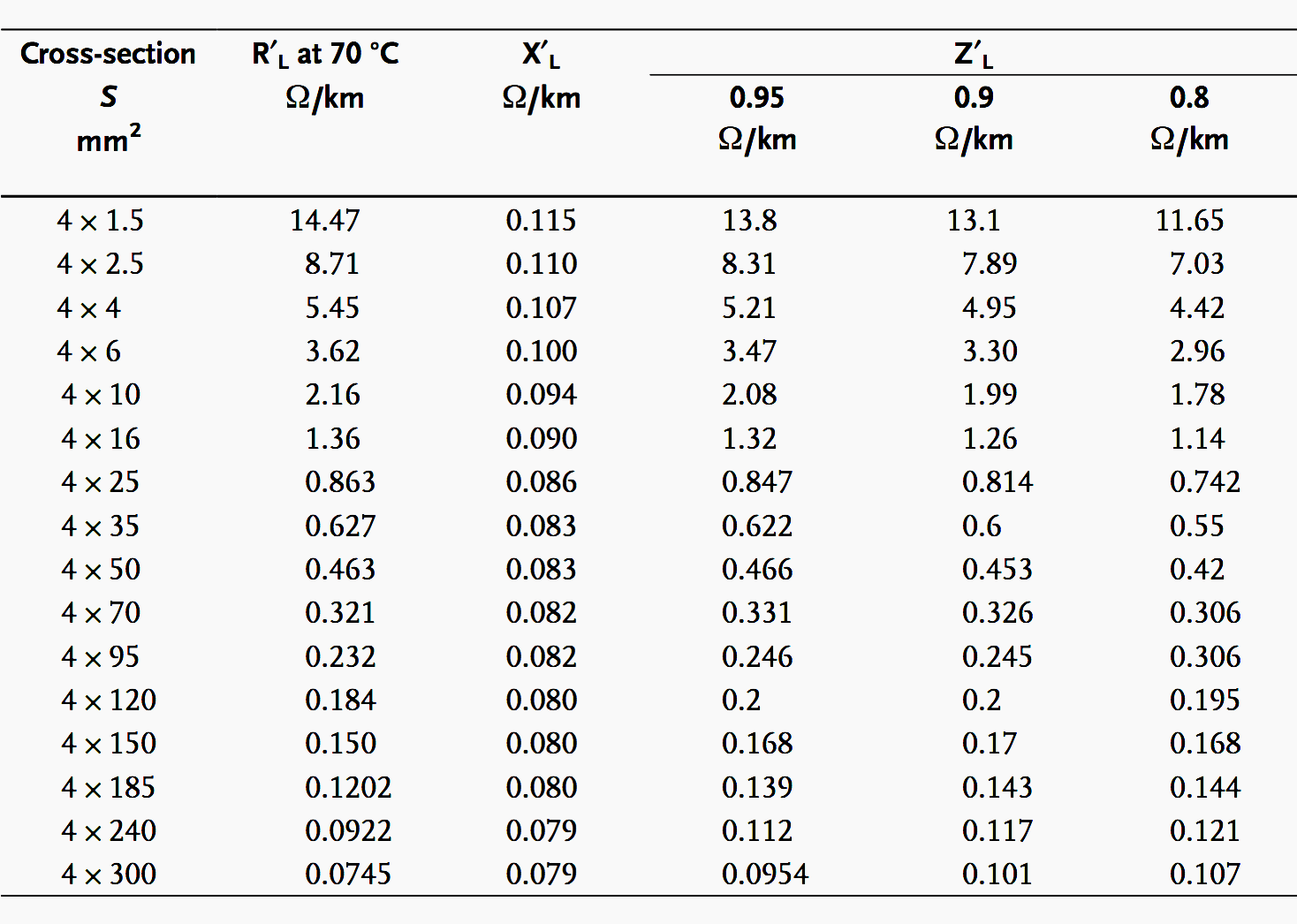
The effective resistance per unit length for 516 A is:
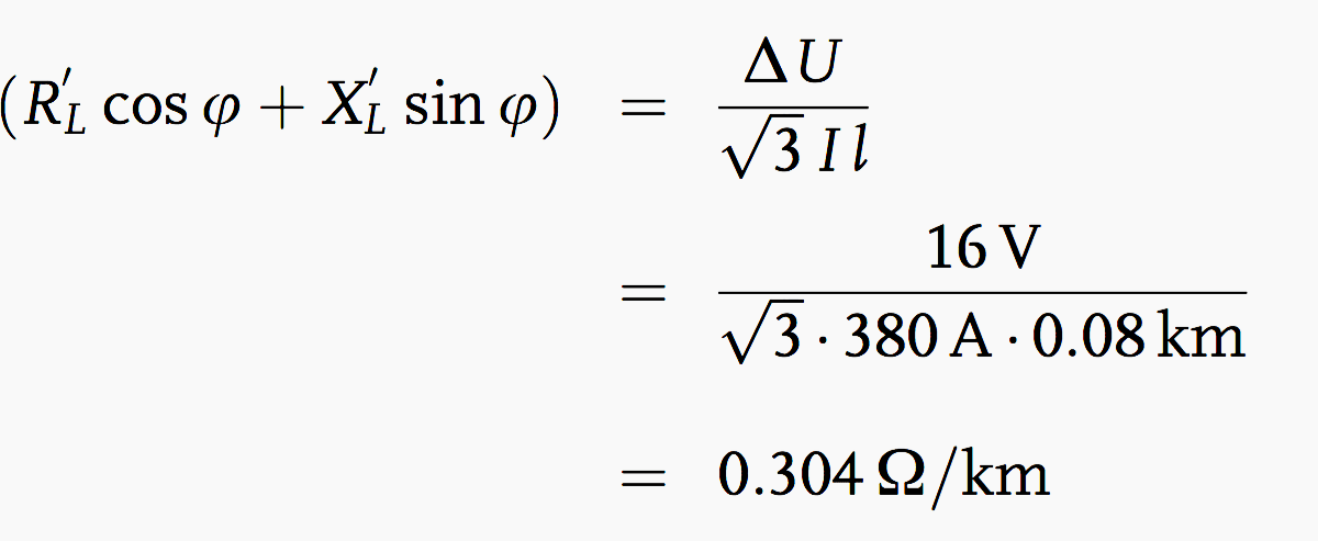
According to Table 2 (see below) we must choose a cable with a cross-section of 4 × 95 mm2. The effective resistance per unit length for 380 A is:
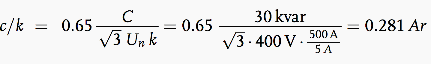
Example 4 – Calculation of the c/k Value
Given a 150 condenser battery, i.e. 5 stages of 30 each, a supply voltage of 400 V, and an instrument transformer with a k of 500 A/5 A, how large is the c/k value? The ratio c/k is given by.
Tables
Table 1 – Multipliers to Determine Capacitor Kilovars Required for Power Factor Correction

Table 2 – Resistance per unit length for (Cu) cable with plastic insulation
References
- Analysis and design of low voltage power systems by Ismail Kasikci (Purchase hardcover from Amazon)
- Power factor correction – A guide for the plant engineer by EATON


Let’s say we had a heater was drawing 10 Amp before power compensation or power factor correction. What will happen to that specific load after correction? will it still draw 10 Amp right since we can not change the Amp for that specific load. Then how lowering the total Amperage wouldn’t affect that load? On other hand, when we lower the total amp what happens to each specific load in terms of their nominal current?
Very informative and detailed
Very informative
Thanks sir you are improve aur knowledge.
Thanks
Thank you a lot
How do we know how many and what kvar load is needed to compensate reactive power .Is there any table ?
thank you for this. this is very helpful.
Thank you Arnel!
Hey, I do not think that the pic b is correct. There are strange angles at Ur.
cos phi = 1 means 0 deg between current and voltage so it is not capacitave nor reactive load but pure resistive.
yes…..cos= 1
means there is no reactive power.
but he is right when we look at the graph diagram, coz of having some degree on cosine.
thank you sir
amazing explanation.
Many thanks Edvard.
This is a good and practical method to get better the performance of the system mainly the losses and voltage regulations. Thank you..
very good.
thanks
very nice thank you
Thank for usefull report