
66 kV and upwards
Capacitive voltage transformers (CVTs) are used on higher voltage levels, starting from 66 kV and upwards. The type of the CVT is always a single-pole one, thus the connection is between phase and earth. The higher the voltage level is, the more price-competitive the capacitive type becomes.
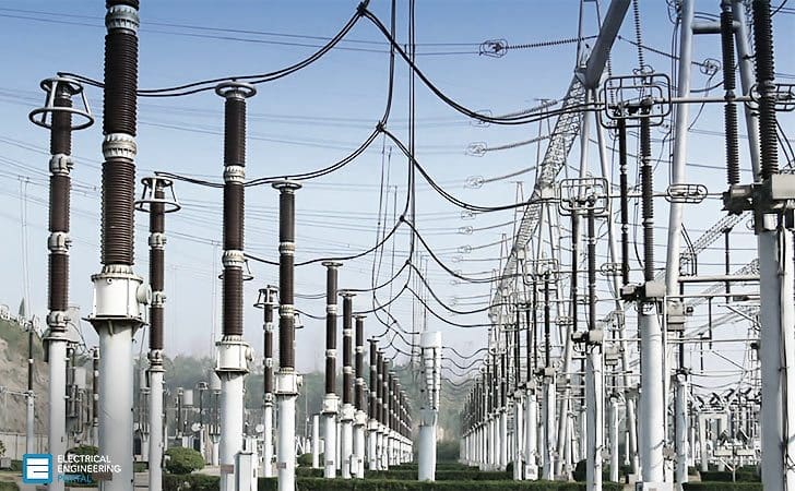 HV Capacitive Voltage Transformers (photo credit: gegridsolutions.com)
One of the advantages the capacitive type has, in comparison to the inductive type, is the possibility to use capacitive voltage transformers as high-frequency coupling units towards the primary system (over headlines).
A typical application would be to utilize the CVTs for power line carrier (PLC) high-frequency signal interface units. For the voltage measurement purposes, the behavior and the data specification of CVTs follow the same guide lines as the inductive ones.
This value is chosen considering the following issues //
- Voltage magnitude to be measured
- Demands from PLC system (frequency, bandwidth, connections)
- Capacitive voltage transformer manufacturing considerations
The construction of capacitive voltage transformers
The figure above shows the principle of a capacitive voltage divider on which the capacitive voltage transformer is based. The trimming windings are used for fine tuning the output signal to correspond with the required accuracy class requirements. The compensating reactor compensates the phase angle shift caused by the capacitive voltage divider.
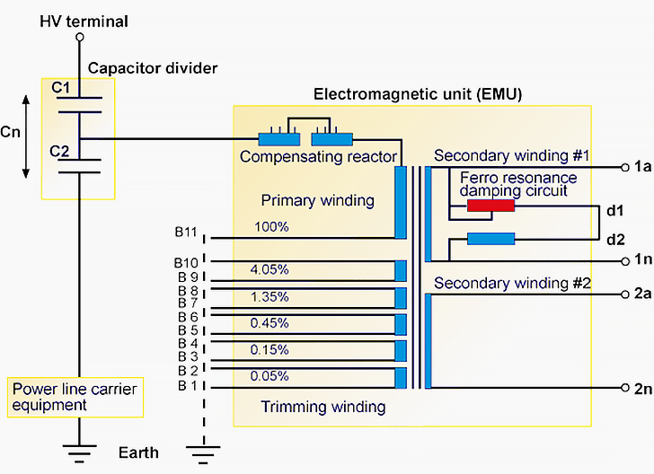
All capacitive voltage transformers require some sort of ferroresonance damping circuit.
The capacitance in the voltage divider, in series with the inductance of the compensating reactor and the wound transformer (inside the electromagnetic unit EMU), constitutes a tuned resonance circuit. Unlike with the inductive type of voltage transformers, the CVTs usually have the ferroresonance damping circuit inbuilt in the CVT itself, as shown in the previous figure.
At higher system voltages, the resonance phenomenon usually takes place on fundamental or on sub-harmonic frequencies, resulting in voltage transformer heating (finally damages) and non-selective operations of protective relaying possible protective relaying non-selective operations.
The circuit consists of a saturable series reactor and a loading resistor. This circuit is connected in parallel to one of the secondary cores. During ferroresonance conditions, high voltages appear, saturating the reactor and turning the damping resistor on to effectively mitigate the parasitic voltage. During normal system conditions, the reactor presents high reactance, effectively “switching off” the damping resistor.
Possible triggering factors for the ferroresonance phenomena could be //
- Planned primary switchings in the system
- Circuit breaker trippings caused by primary fault
- High-speed autoreclosing
Reference // ABB’s Distribution Automation Handbook


Can you advise please, During erection of 220 kv Capacitive Voltage transformer, we should connect the CVT and Coupling Capacitor,
Shall we remove pressure release valve cap before connecting both unit together Or we should keep pressure release valve as it is and coupled bothe unit by nuts and bolts that it.
Kindly guide me.
Thanks.
as an diploma junior engineer what i’ve to learn
I am looking to get a bit more educated on the application and maintenance testing requirements for these CVT’s. Also, recommended Commissioning test requirements.
Dear Sir,
I have a question about CVT. In a 400kv high voltage substation with one & half breaker system, there are 4 CVTs for BB1,BB2,Node1, Node2 and 3 circuit breaker Q01,Q02,Q03. For closing of CBs there is one protection relay 6MD664 for synchronization that has one 3 phase analogue voltage input(V1,V2,V3,VN) and one single(V4) phase. Question: can apply 3 independent CVTs to 3 phase analogue voltage input(V1,V2,V3,VN)?if so , the 4th cvt will be applied to V4 input of relay.
Hi,
This is Dhinesh, just telme how to calculate the magnetizing reactance value of EMU Unit? And then primary and secondary impedance of EMU Unit?? There’s any formula for that means telme as soon as possible!!!!
Very educative article on Capacitive Voltage Transformers otherwise what could be the life time of these transformers?
If a name plate value of a capacitor is C1=9800, and C2= 78000, what is the effect of larger capacitances for either one of these capacitors? Is it solely an effect on the divider, or will an error happen on the step relaying function?
Now we design out High voltage Screw Ceramic Capacitor,
500PF 24KVAC, ø25x44mm
Withstand Voltage 50KVAC
Lightning impulse up to 120KVAC
This capacitor is important components of capacitive coupler.
Datasheet can be send on request.
Dear Sir,
Now, Coupling capacitor of CVT in EHV system are not of any use as State Power Utilities are preferring OPGW cable for communication and lightning protection of transmission line, therefore, now we should go for VT instead of CVT or not as function of Voltage Transformers now end with protection and metering. What are the demerits if we prefer VT instead of CVT at line terminating point. Also clarify whether CVTs are costly than Vts or not.
Requesting for an early reply.