
Problems with capacitor banks
Some of the failure problems associated with capacitor banks are already known since they happen often. A few of the failures are traceable to the original source and sometimes that may be difficult to do. In many instances, the final result of a failure may be a catastrophic explosion of the capacitor into pieces or fire.
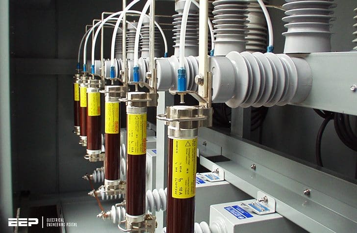
 15 bad situations that may lead to catastrophic explosion of a capacitor bank (photo credit: Juan Guevara via Flickr)
This technical article discusses potential fire and explosion hazards with capacitor banks. The 15 most typical causes for capacitor failure are discussed below.
1. Capacitor failure due to inadequate voltage rating
In the filter banks, the capacitor units are connected in series with inductors. Sometimes the voltage across the capacitor units exceeds the design values. In such circumstances, the capacitor units fail catastrophically due to inadequate voltage rating.
2. Fuse blowing
The blowing of a fuse may be due to short circuit in a capacitor unit, overcurrent due to an overvoltage, or harmonics. A short-circuited capacitor unit can be determined by inspecting the capacitor can for bulging or case rupture.
Thus a fuse that blows after a capacitor short is not classified as a fuse failure.
Fuse failure may occur due to fatigue, incorrect application, and improper branch protection.
3. Thermal failure
Capacitors operated at extreme hot conditions can fail due to excessive temperature. The excessive heat can be due to high ambient temperature, radiated heat from adjacent equipment, or extra losses.
4. Ferroresonance
The capacitor banks tend to interact with the source or transformer inductance and produce ferroresonance. This can produce undamped oscillations in the current or voltage, depending on the type of resonance.
If the system is not adequately damped, then there is a possibility of capacitance or transformer failure. This is due to the system condition and cannot be identified by visual inspection.
5. Harmonics
Any nonlinear load in the system such as an arc furnace or converter equipment produces harmonics. Filters are used to control the harmonics.
It’s very important that capacitor banks are installed on the best possible location in the network.

6. Open circuited capacitor units
Field measurement can determine if the fuse is blown and if there is an open circuit due to capacitor failure.
7. Dielectric failures
When an internal series group of a capacitor unit fails, the voltage on the remaining internal series groups in the string increases.
It is desirable to remove the bank from service when the voltage applied to the remaining internal series groups exceeds 110% of their rated voltage.
It is important to note that as the internal design of the capacitor units used in fuseless banks becomes an integral part of the relay scheme, replacement of faulty units in a bank should be made only with units sharing the same internal electrical configuration.
Learn here in details unbalance detection schemes for removing failed capacitor bank from the system.

8. Rack faults and insulation failures
The two failure modes of greatest concern in a fuseless bank are the failure of a unit’s major insulation and the flashover of a unit’s bushing. If a unit in an externally fused bank experiences either of these two failure modes, the external fuse will operate and remove the unit from service.
However, fuseless banks have no external fuses.
9. Manufacturing defects
Yes, it happens, just like in the car industry or any other industry. It’s important to notify the capacitor manufacturer as soon as possible.
These defects are to be identified during the testing of capacitor units in the factory. The typical bathtub curve of failure of any electrical component is shown in Figure 4.

The bathtub curve consists of three periods:
- An infant mortality period with a decreasing failure rate;
- Then a normal life period, also known as useful life with a low, relatively constant failure rate; and finally,
- A wear-out period that exhibits an increasing failure rate.
If there are any manufacturing defects in the capacitor units, the failure SHOULD occur in the factory during testing, but not necessarily. During useful life, any capacitor failure may be due to stress-related causes.
10. Failures due to internal stress in the capacitor units
The application of ripple currents, surge voltages, and high frequency oscillatory currents can cause internal stress in the capacitor units and premature failure.
Figure 5 shows how the ripple current affects the life of capacitors.
In addition to ripple current and overvoltages, the type of waveforms and duration of the current pulses also affect the life of the capacitor units.

11. Failures due to external stress
Sometimes the capacitor banks are exposed to extreme operating conditions, including excessive ambient temperatures, humidity, temperature cycling, vibrations, shock, and lack of ventilation. Such conditions can occur in substation capacitor installations.
In certain applications, forced air cooling is used.
In many applications, the capacitor banks are exposed without any forced air cooling. Extra cooling of these units is expected to improve the life expectancy.
12. Human error
Sometimes human error is responsible for capacitor bank failure. If the protection coordination of the fuse selection is not performed correctly, fuse or capacitor failure may occur.
To perform this operation correctly, the circuit switcher is opened. Then the circuit breaker is closed. The energization of the capacitor bank is performed using the circuit switcher with closing resistance in the circuit.
Such human error is common but very difficult to prove, unless the operator admits or records such error.
13. Surge arrester connection
The surge arrester is connected across the filter bank for protecting from switching and lightning surges. Sometimes the surge arrester is connected across the reactor as shown in Figure 7.

In such a connection, during overvoltage, the surge arrester conducts and forces large currents through the capacitors.
The recommended connection of the surge arrester in a filter bank is shown in Figure 8. Applying a surge arrester in an ungrounded wye connection has other performance issues as outlined in IEEE Standard C62.22.

A solidly grounded filter circuit with surge arrester across the filter circuit is recommended.
14. Converter harmonic production and related issues
If the converter produces more than acceptable harmonics, the filter components such as capacitor and inductor will be overloaded, leading to premature failure.
Even harmonics can be created in rectifier systems by firing irregularities.
15. Failure problems associated with the H-configuration capacitor banks
Consider an H-capacitor bank as shown in Figure 19.8. Each quadrant of the bank consists of several series–parallel capacitor units.
The H-configuration is used in order to identify the failure in the groups using the resultant current through the bridge. When one element fails, it produces a temporary short circuit.
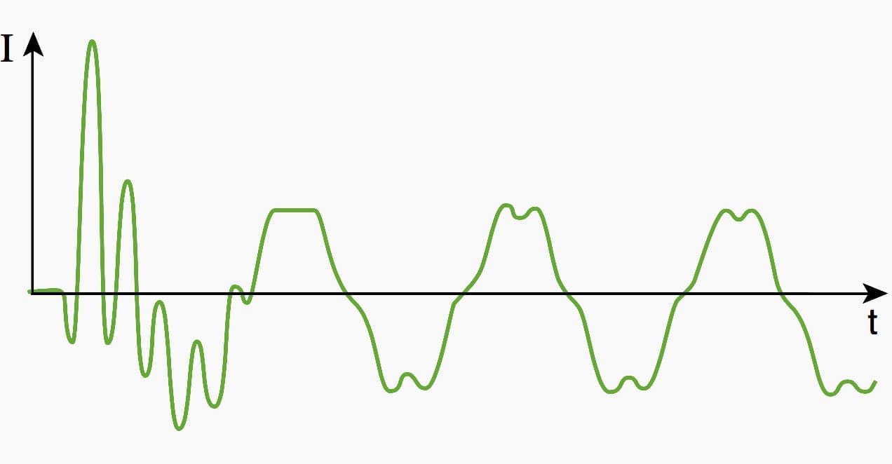
The measured current on the secondary of the current transformer is shown in Figure 9.

It can be seen that the peaky short-circuit current remains for a duration of 50 ms. Then the adjacent elements discharge into the failed element and the fuse blows under excessive current.

The unbalance current decays and settles to a lower value. If the value is large enough to produce an alarm or a trip signal, then there will be some activity to protect the bank. If the capacitor elements fail in adjacent quadrants, then there will be a cancellation effect on the unbalance current level.
Therefore, if elements are failing in the adjacent quadrant, the alarm or trip settings for unbalance protection may not be effective.
Following scheme is applicable to double Wye-configured banks.
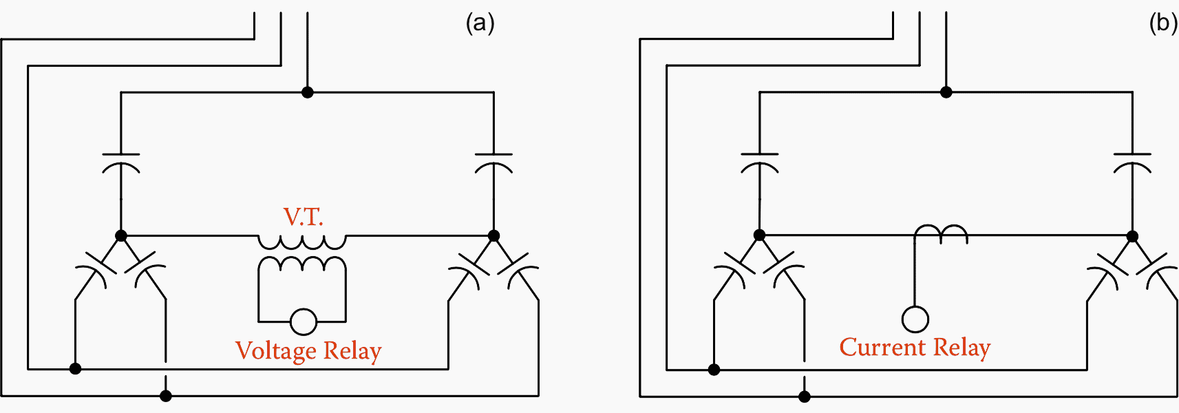
A similar scheme can be applied on a phase-by-phase basis when multiples of four capacitor units are connected in “H” configuration with the current transformer (or voltage transformer) connected in the connection between the midpoints of the two pairs of capacitors that make up the “H”.
Sources //
- Power System Capacitors by Ramasamy Natarajan
- Industrial power systems by Khan, Shoaib
- Design and use of MV current-limiting fuses by O. Bouilliez and J.C. Perez Quesada


Thank you Edvard for such a concise and simple explanation, it is a treat to read your articles on many topics of Electrical Engineering, keep it up. 👍
Regards
Hello
the risks of damage to the capacitor banks due to atmospheric overload are not eliminated,
in medium voltage level HTA the protection of these batteries being ensured not by fuses but by digital protections (I speak of the country in which I reside) which monitors the current imbalance through a toroid or current transformers in addition to minimum and maximum voltage thresholds
in the event of a fault, the protection trips the circuit-breakers enclosing the battery and de-energizing it.
the circuit breaker can be used from a cell of a span and feeds the battery by cables,
the bay may be of type shielded for example that of the manufacturer SIEMENS or the battery is delivered with the complete kit circuit breakers and protections and located in an enclosure reserved for this purpose model of ABB as an example.
despite these provisions, the risk of damage in severe conditions or equipment are solicited by atmospheric constraints such that lightning is not zero especially if it is combined with closing opening maneuver whether by automatic reclosing or by a voluntary closure operated by the operator on other departures.
this can be a serious damage to the battery see its destruction by fire.
in summary in high voltage whether it is level A or level B; it is better to invest in taste and surveillance with digital protections instead of fuse and I think that each country adopts in its own way the method of protection that suits it; but the one that must dominate normally is the one that has made these proofs throughout the world and in different working conditions.
I thank you for your contributions.
Greetings
Hi I’m working for Eskom I’m involved with capacitor banks for sometimes now I had problems of hot connections
Most probably it is due to high levels harmonics, please carry out harmonic surveys using good make PQ Analyser.
Dear sir,
Our load is mostly welding machines+other rotators, so the power factor goes down and then the Electricity bill is more, please tell me to improve it by capacitor and connections.
our total load is 2 MVA, so what is the size of the capacitors.
The general thumb rule is the Capacitor bank rating should be minimum 1/3 of total load, however you also need to consider initial/existing PF and target PF.
Thank you for the valuable technical information that you share. I am already a retired electrical engineer and but I still would very much like to get more reference information. I truly appreciate your kind help, and hopefully can enroll in your premium membership with EEP in the future.
Very much useful information.please keep sending such chapter
Dear Sir,
I am Tandyala Ramachandrarao studying Electrical Engineering, I cannot afford for premium membership,
could you please give a book of
ELECTRICAL DESIGN CALCULATIONS FOR INDUSTRIAL PLANTS. by mail.
[email protected]
or [email protected]
ph :- +919491494946
thank you.