


Estimated Study Time: 10 minutes
Introduction to capacitors
Capacitors are used in industrial premises for two basic functions: the first, to correct the load power factor, usually to meet the supplying authority’s supply requirements and avoid tariff penalties if the required power factor is not met, and the second, to correct voltages within the plant.
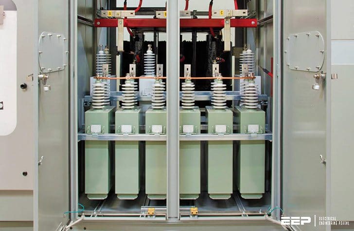 Medium Voltage Capacitor Banks (photo credit: powersurvey.com)
Individual capacitors can also be attached to circuits feeding loads with inherently low power factors to correct for their low power factor and so improve both the overall plant’s net power factor and, at the same time, reduce the voltage drops within the plant.
Capacitor banks and individual capacitors can therefore form either fixed installations, which are always connected when that section of the plant is running, or be switched when required. A common example of application is capacitors connected directly in motor circuits that are switched with the motor and keep the net power factor for each motor circuit at an ideal level.
Switched individual units or controlled banks are used where conditions vary, either within the plant or on the in-feeding supply system, and where a variable reactive power level needs to be compensated. Capacitors can only be manufactured as relatively small elements, both in terms of their reactive power rating and their operating voltage.
Capacitors used in electrical systems are therefore supplied as capacitor units, also known as capacitor “cans,” which are made up of a number of series and parallel internal elements to obtain practical levels of reactive power rating (kVAR) and of service and withstand voltages.
Capacitor application
Capacitor Construction
Capacitor units are supplied in three basic configurations: externally fused, internally fused, and fuseless designs.
The externally fused design, which is used for most small and individual applications, is designed to rupture the external fuse for the failure of one individual element within a capacitor unit.
In the internally fused design, each capacitor element within the capacitor unit is individually fused, and the failure of an individual element ruptures that particular fuse so that the capacitor unit can remain in service.
The third type, the fuseless capacitor, is designed so that any element failure produces a stable short circuit in the element that can carry the current of other elements connected with it in series. Again, this design of a capacitor unit can continue to be operated with some individual elements failed.
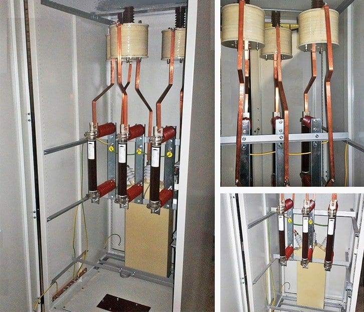
Externally fused units can be used individually or in self-protected groups, whereas the other two types are usually used within large capacitor banks in series/ parallel configurations.
Banks made up of these and externally fused units require external circuit protection and overall monitoring to ensure that the individual units that make up the bank are not overstressed when more internal elements fail within the individual units or when additional fuses on the externally fused units rupture.
1. Individual Capacitors
Individual outdoor capacitors are usually designed for rack mounting on an insulated structure, using individual or group fusing, together with accessories such as switching devices and control facilities.
Such capacitors can be provided for operation at voltages less than or equal to 2.4 kV and for reactive power ratings up to 1200 kVAR. Enclosed housings are also available for units in the above voltage range up to 600 kVAR.
2. Motor Capacitors
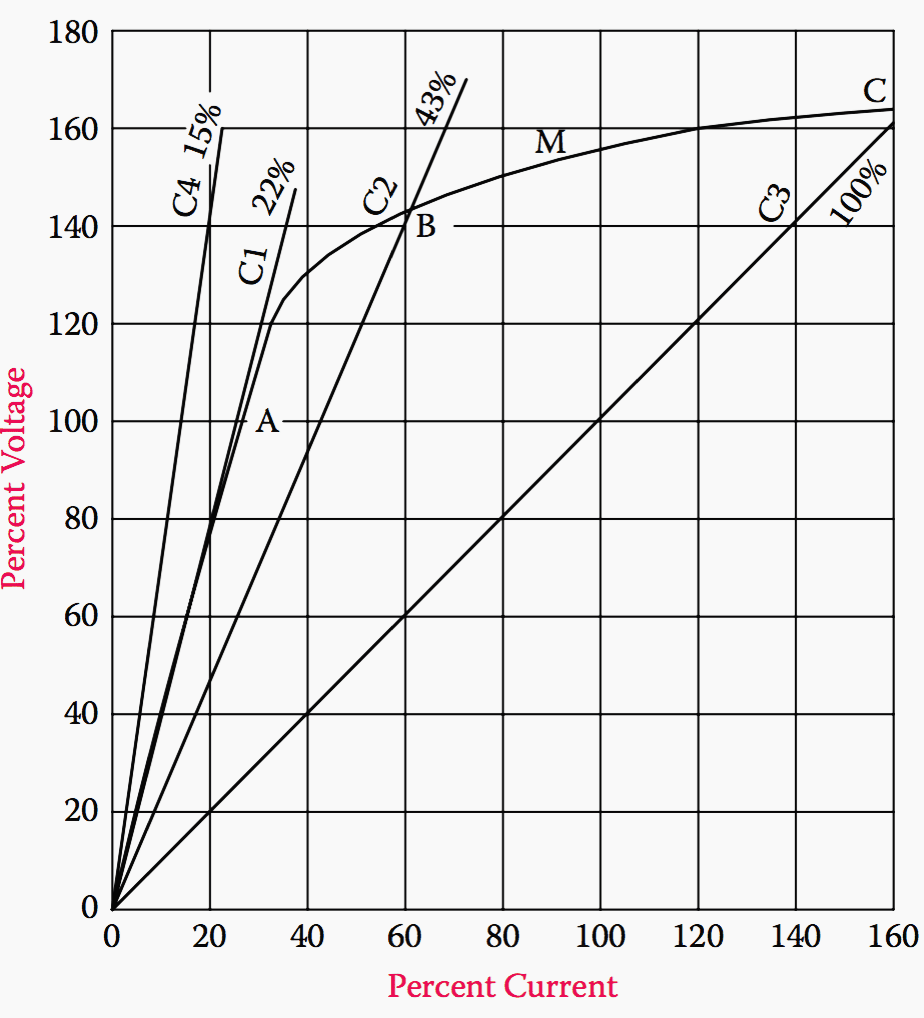
Capacitors for individual motor application are available for standard voltages and in the range of 2.5–600 kVAR, three phase. These are used to correct the motor power factor individually, but when such capacitors are coupled with induction motors, there can be overvoltages due to self-excitation, as shown in Figure 1.
In this figure, the straight lines show the capacitor rating in percentage of the motor rating, and the intercept points A, B, or C on the M curve show the percentage overvoltages expected with that particular capacitor rating.
Interesting Fact About Capacitor Start Induction Motors
3. Switched Capacitors
For any switched-capacitor scheme, the switching devices must be rated for capacitor switching and have a voltage rating greater than the associated maximum system operating voltage. The device-interrupting rating must exceed the system short-circuit rating and must also interrupt the capacitor current without producing excessive transient overvoltages.
A typical medium-voltage industrial installation is shown in Figure 2 below.
This type of capacitor bank design completely encloses the bank’s components within a grounded structure, which eliminates the need for a fenced enclosure and mitigates rodent and pollution problems.
Enclosed capacitor banks are more aesthetically pleasing compared with air-insulated open-rack capacitor banks. The capacitor bank assembly is furnished with fused capacitor units, insulators, current-limiting reactors, vacuum switches, main-line fusing, line disconnect switch and grounding switch, surge arrestors, and instrument transformers.
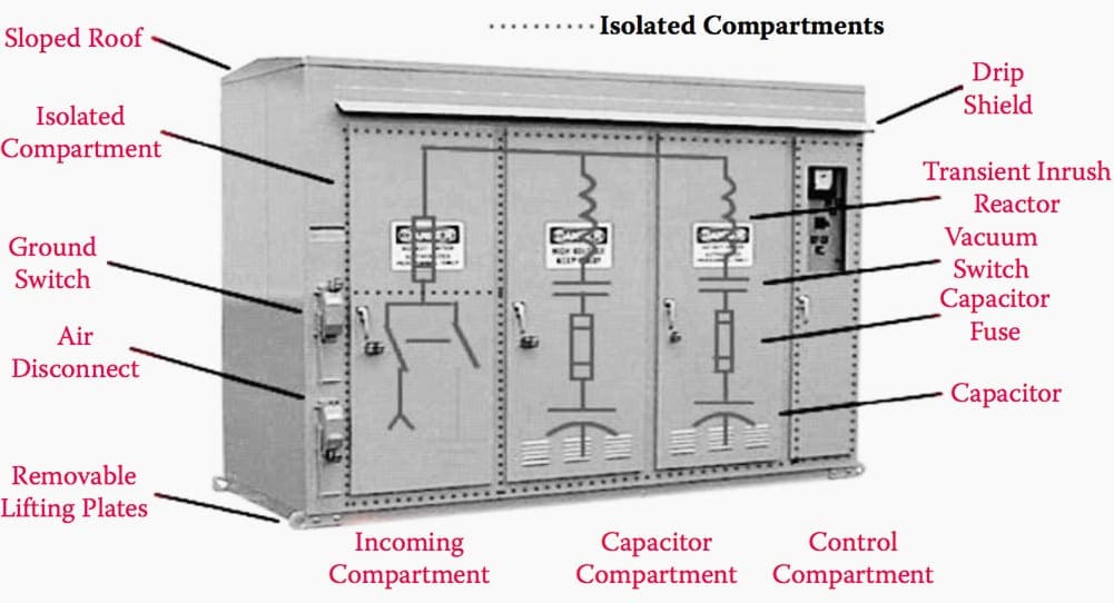
A separate section is provided for the protection, monitoring, and control devices together with a separate cable- entrance section.
The doors of the enclosure are key interlocked to prevent entry into a live compartment. Enclosed capacitor banks often use internally fused capacitor units, as these are compact in design and more reliable compared with externally fused capacitor units.
Switching Device Rating
The momentary rating of the switching devices should withstand short-circuit currents for faults and the high-frequency inrush currents associated with switching capacitors. The maximum transient current and net inrush frequency have to be calculated for the more severe of the following two conditions:
Isolated bank switching
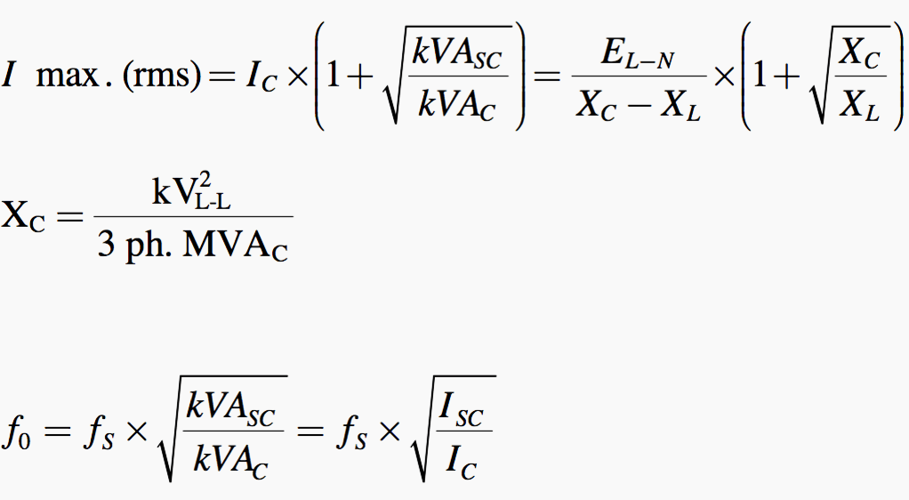
Back-to-back switching
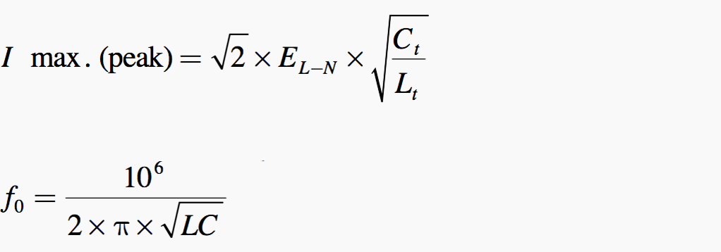
where the subscripts “sc” and “c” refer to the short-circuit infeed and capacitor values, respectively, while f0 is the inrush frequency and fs is the system frequency.
The formulae to use in other cases are summarized in IEEE C37.012.
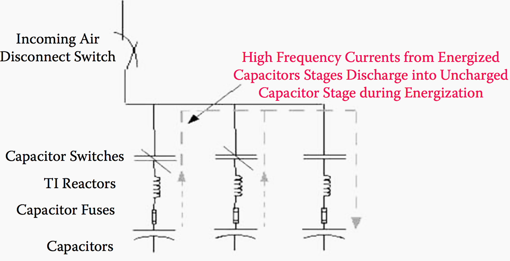
Transient inrush reactors, which are designed to increase the life expectancy of capacitor switches by limiting both the magnitude and frequency of the transient inrush currents associated with back-to-back capacitor bank switching, can be added.
In these cases, the switches are usually rated 200–600 A, with a 200 A single-phase group- operated switch being the most common.
Related electrical guides & articles



Edvard Csanyi
Hi, I'm an electrical engineer, programmer and founder of EEP - Electrical Engineering Portal. I worked twelve years at Schneider Electric in the position of technical support for low- and medium-voltage projects and the design of busbar trunking systems.I'm highly specialized in the design of LV/MV switchgear and low-voltage, high-power busbar trunking (<6300A) in substations, commercial buildings and industry facilities. I'm also a professional in AutoCAD programming.
Profile: Edvard Csanyi
please you can give me samo catalog of capacitor for MV and HV
Nice, answers
I’m an Electrical engineer