
Estimated Study Time: 14 minutes
Compensation capacitors
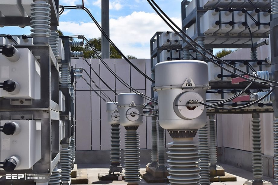
Compensation capacitors are installed in numerous locations in electrical installations. They are to be found in high voltage transmission and distribution systems, in transformer substations and also at various levels in low voltage installations. Capacitors therefore have to be made in accordance with very diverse technical specifications, for powers ranging from a few kvar to several Mvar.
 Connections and composition of LV/MV/HV capacitor banks
Installing capacitors in electrical systems fulfils several functions. Although the most well-known is power factor compensation, they also improve the voltage regulation of transmission lines by reducing the voltage drop and increase the capacitive component of lines that are naturally inductive.
Capacitor banks are made up of capacitor units wired, protected and connected together according to different connection modes appropriate to each type of use. Each of these modes has advantages and disadvantages.
It should also be noted that numerous detection systems (current or voltage relays, controllers, etc.) are used with capacitor banks to detect (alarm threshold) and eliminate dangerous situations that could occur, like unbalance, cascading damage, etc.
1. Connections of capacitor banks
1.1 Delta connection
This is the most commonly used connection mode for capacitor banks with voltages lower than 12 kV. This configuration, which is used in particular in distribution installations, provides maximum reactive power in minimum dimensions. The compensation balances itself “naturally” if there is current unbalance or phase shifting of one phase in relation to another (presence of powerful single-phase receivers).
The capacitors must be insulated for the full voltage (connection between phases), and if there is a breakdown the consequence is that the fault current is high as it is the result of a phase-to-phase short circuit.
1.2 Star connection, neutral not connected
Star connection has a number of technical advantages in relation to delta connection, but it is less favourable from an economical point of view. Amongst other things it can block zero sequence currents. As the capacitors are subject to phase-to-neutral voltage, their value must be multiplied by 3 to obtain the same reactive power as in delta connection.
Their insulation voltage must nevertheless be provided for the phase-to-phase voltage to avoid the breakdown of one branch causing another branch to break down.
This is the main drawback of this layout, where the loss of capacitor elements may not be detected, leading to load unbalance and no compensation. For this reason, double star connection is preferable.
1.3 Double star connection, neutral not connected
This type of wiring is suitable for all powers and all voltages of capacitors. It retains the advantages of star connection, and adds a protection mode enabling internal faults to be detected.
An unbalance protection device (transformer and current relay) continuously monitors the unbalance current between the two neutral points and if necessary triggers the disconnection of the bank.
High voltage capacitor banks are composed of elementary capacitors, generally connected in several serial-parallel groups, providing the required electrical characteristics for the device.
The nominal insulation voltage of the bank depends on the number of groups in series, while the power depends on the number of elementary capacitors in parallel in each group.
1.4 Star and double star connections, neutral earthed
Connections with earthed neutral provide better protection against transient overvoltages (lightning) and against electromagnetic disturbance in general. However, resonances and zero sequence currents can be produced if there is a fault either as a result of internal breakdown or loss of a supply phase.
These configurations require protection against overvoltages and unbalance.
1.5 H connection
H connection can be used for delta or star single-phase or three-phase connections. The schematics below represents a branch between two phases or between phase and neutral.
This type of wiring is intended for high power HV capacitor banks. For three-phase capacitor banks, the unbalance is monitored on each phase. It provides greater current unbalance measurement sensitivity.
2. Internal faults in capacitor banks
2.1 Protection by pressure monitoring device
In addition to or instead of fuses, and depending on the required protection conditions, capacitors can also be protected using a pressure switch that detects increased pressure in the case, generated by the breakdown of the elementary capacitances.
A contact feeds back the measured state to trigger the breaking of a protection device.
2.2 Protection using internal fuses
When an internal fault affects one or more elementary capacitors, it is important to detect this fault and eliminate it as quickly as possible to avoid avalanche breakdown of the bank. If there is a fault in an elementary capacitor, the corresponding internal fuse eliminates the faulty element.
Given the large number of elementary capacitors that make up the device, the resulting loss of power is negligible (less than 2%).
Used with fuses, protection based on maintaining the symmetry (see Figure 8), enables detection of an unbalance that corresponds to a number of faulty capacitors. The adjustment threshold, precisely defined by the manufacturer, sets maximum operating conditions with a view to ensuring maximum reliability and continuity.
Where:
- Discharge resistor
- Internal fuse
- Elementary capacitance
2.3 “All film” HV capacitors
Each elementary capacitance is made using two aluminium foils forming the armatures insulated by a high dielectric quality polypropylene film.
After being dried, treated and impregnated under vacuum with a non-chlorinated, non-toxic, biodegradable liquid dielectric, all the interconnected elements are placed in a stainless steel case, with porcelain terminals or insulated feed-throughs at the top, for connecting the device.
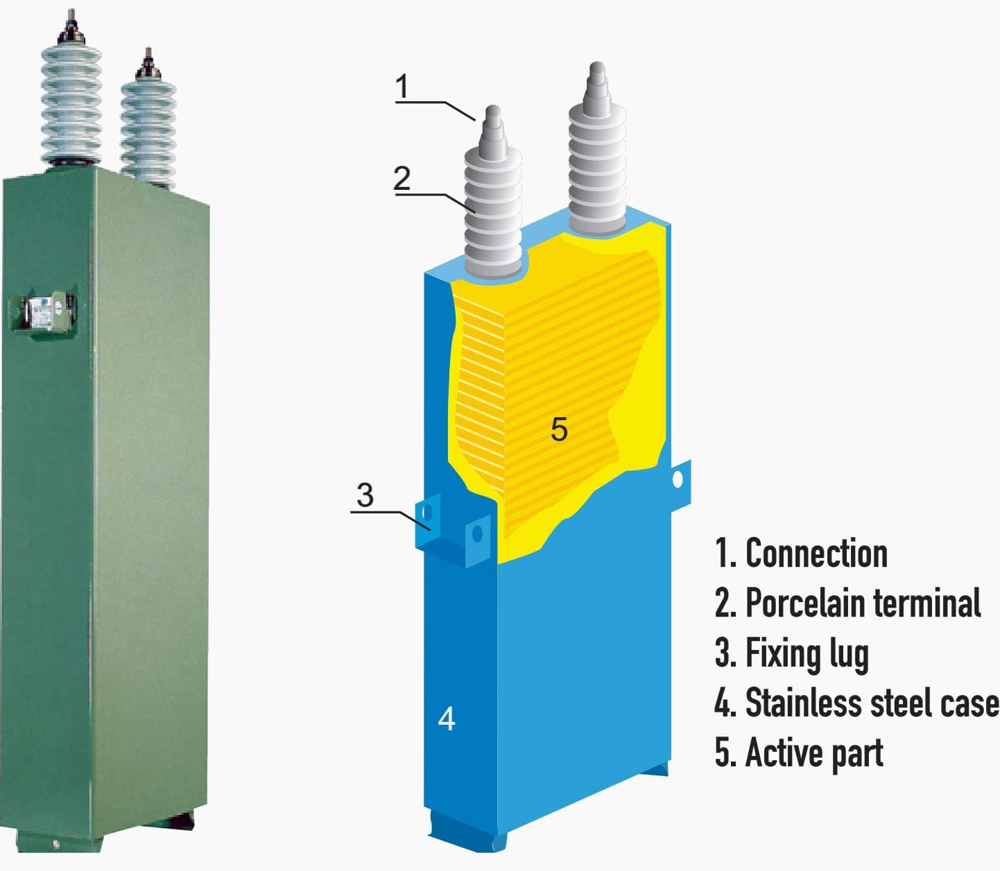
This “all film” capacitor technology has top quality characteristics: excellent resistance to electrical fields, very low ohmic losses limiting temperature rises, a much longer service life than with previous technologies using paper, and excellent resistance to transient overcurrents and overvoltages.
With the polypropylene film, the liquid dielectric, which has a remarkably high chemical stability, a high gas absorption capacity and a high partial discharge extinction capacity (flash point approximately 150°C), ensures total insulation between electrodes.
Table 1 – Technical characteristics
| Average loss factor | on energization: | 0.15 W/kvar |
| after 500 hours’ operation: | 0.10 W/kvar | |
| Average variation of the capacitance as a function of the temperature | 2×10⁻⁴ °C | |
| Operating frequency | Standard: | 50 Hz |
| On request: | 60 Hz | |
| Permissible overloads | Permanent: | 1.3 In |
| Permissible overvoltages | 12 h/24 h: | 1.1 Un |
| 30 min/24 h: | 1.15 Un | |
| 5 min/24 h: | 1.2 Un | |
| 1 min/24 h: | 1.3 Un | |
3. Composition of LV capacitor banks
A distinction is made between fixed value capacitor banks and “step” (or automatic) capacitor banks which have an adjustment system that adapts the compensation to the variations in consumption of the installation.
3.1 Fixed capacitor banks
With constant power, these are suitable for individual compensation at the terminals of receivers (motors, transformers, etc.) or more generally for installations where the load is constant and fluctuates very little.
3.2 Step capacitor banks with automatic regulation
This type of device enables the reactive power supplied to be adapted to variations in consumption, thus keeping the compensation at its optimum value. It is used in situations where the reactive power consumption varies considerably and is high in relation to the power of the transformer. Such situations are encountered at the terminals of main LV distribution boards or at the origin of high power outgoing lines.
Switching all or part of the capacitor bank on and off is controlled by an integrated power factor controller.
The capacitors will therefore only be activated after the motor starts. Likewise, they may be disconnected before the motor is switched off.
The advantage of this system is the ability to totally compensate the reactive power of the motor at full load. An optional damping reactor should be provided if several capacitor banks of this type are installed on the same system.
3.3 Capacitor banks with separate control
It may be necessary to have separate switching of a capacitor bank to avoid overvoltages, by self-excitation or when a motor starts, using a special device:
- Rheostat,
- Change of coupling,
- Reactors,
- Auto-transformer,
- etc.
3.4 Conventional rule for selecting the capacitor bank technology
Fixed compensation has the risk of over-compensation which increases the operating voltage abnormally. Automatic compensation avoids permanent overvoltages resulting from over-compensation when the system has a very low load a steady operating voltage is thus maintained, avoiding the additional cost of billed reactive energy.
If the power of the capacitors (in kvar) is less than 15% of the power of the transformer (in kva), choosing a fixed capacitor bank will definitely provide the best cost/savings compromise.
If the power of the capacitors (in kvar) is more than 15% of the power of the transformer, a step capacitor bank with automatic regulation must be chosen.
Source: Electrical energy supply by Legrand
Related electrical guides & articles


Edvard Csanyi
Hi, I'm an electrical engineer, programmer and founder of EEP - Electrical Engineering Portal. I worked twelve years at Schneider Electric in the position of technical support for low- and medium-voltage projects and the design of busbar trunking systems.I'm highly specialized in the design of LV/MV switchgear and low-voltage, high-power busbar trunking (<6300A) in substations, commercial buildings and industry facilities. I'm also a professional in AutoCAD programming.
Profile: Edvard Csanyi

if we connect 3 nos 200 KVAR 4.2 KV single phase capacitor bank then what will be the net value of capacitance
[email protected]@gmail.com
Thank you for those informations
I need an example of installation of bank capacitor in LV please
I have studied substations my entire life and am so glad to have found this portal into my passion. Looking at a 230kV 3PH 60Hz capacitor bank in a branch substation as a kid hearing the crackle, feeling the shear energy is a powerful memory that is coming to light as far as characteristics go. Always wondered the rating of said bank, always assumed 230,000 VAC but now I know each phase would be rated at approx 750,000 VAC. uF rating was always the big question and now that has moderately been answered as well, much lower than previously thought. 1-10 uF per phase I’m guessing. The really intriguing thing I’ve just learned would be cascading at said voltages. If those individual 30kV capacitors were switched by say an air gap from parallel to series the voltages would obv be in the multi million range. Imagining “the old days” before individual fusing and what those engineers/electricians have witnessed is frightening.
Thank you for the insightful blog here very much appreciated, Martin