
Estimated Study Time: 10 minutes
Capacitance
When a charge is delivered to a conductor its potential is raised in proportion to the quantity of charge given to it. At a particular potential a conductor can hold a given amount of charge.
Capacitance is the term to indicate the limited ability to hold charge by a conductor.
- Let charge given to a conductor be = q
- Let V be the potential to which it is raised.
Then q α V, or
q = CV
C is constant for a conductor depending upon its shape size and surrounding medium. This constant is called capacitance of a conductor.
If V = 1 Volt than C = Q, and Q = 1 Coulomb than C = 1 Farad thus one Farad is capacitance of a capacitor which stores a charge of one coulomb when a voltage of one volt is applied across its terminal.
Capacitor
A capacitor or condenser is a device for storing large quantity of electric charge. Though the capacity of a conductor to hold charge at a particular potential is limited, it can be increased artificially. Thus any arrangement for increasing the capacity of a conductor artificially is called a capacitor.
- Capacitors are of many types depending upon its shape, like parallel plate, spherical and cylindrical capacitors etc….
- In capacitor there are two conductors with equal and opposite charge say +q and –q. Thus q is called charge of capacitor and the potential difference is called potential of capacitor.
Principle of Capacitor
Let A be the insulated conductor with a charge of +q units. In the absence of any other conductor near A charge on A is +q and its potential is V. The capacity of conductor A is therefore given by:
C = qV

If a second conductor B is kept closed to A than electrostatic induction takes place. –q units of charge are induced on nearer face of B and +q units of charge is induced on farther face of B. Since B is earthed the charge +q will be neutralized by the flow of electrons from the earth.
Potential of A due to self charge = V
Potential of A due to –q charge on B = -V’
Thus net potential of A = V + (-V’) = V -V’ which is less than V
Hence potential of A has been decreased keeping the charge on it fixed, hence capacitance has been increased.
Therefore capacity of A to hold charge (Capacitance) is increased.
Dielectric Strength
The material between the two conductors A and B as shown in figure above is always some dielectric material. Under normal operating conditions the dielectric materials have a very few free electrons. If the electric field strength between a pair of charged plates is gradually increases, some of the electrons may be detached from the dielectric resulting in a small current.
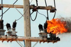
When the electric filed strength applied to a dielectric exceeds a critical value, the insulating properties of the dielectric material gets destroys and starts conducting between the two conductors A and B.
This is called breakdown of dielectric which is fault condition for a capacitor bank. The minimum potential gradient required to cause such a break down is called the dielectric strength of the material. It measures the ability of a dielectric to withstand breakdown. It is expressed as kV/mm.
It is reduced by moisture, high temperature; aging etc. Below table gives dielectric strength of some dielectrics.
| Si.No. | Dielectric Material | Dielectric strength [kV/mm] |
| 1 | Air | 3 |
| 2 | Impregnated Paper | 4 – 10 |
| 3 | Paraffin Wax | 8 |
| 4 | Porcelain | 9 – 20 |
| 5 | Transformer Oil | 13.5 |
| 6 | Bakelite | 20 – 25 |
| 7 | Glass | 50 – 120 |
| 8 | Micanite | 30 |
| 9 | Mica | 40 – 150 |
Dielectric Strength for capacitor is the maximum peak voltage that the capacitor is rated to withstand at room temperature. Test by applying the specified multiple of rated voltage for one minute through a current limiting resistance of 100 Ω per volt.
Sizing of Capacitor banks for power factor improvement
The Power Factor Correction of electrical loads is a problem common to all industrial companies. Every user which utilizes electrical power to obtain work in various forms continuously asks the mains to supply a certain quantity of active power together with reactive power.
- Resistive
- Inductive
- Capacitive
The most common of these on modern systems is the inductive load. Typical examples includes transformer, fluorescent lighting, AC induction motors, Arc/induction, furnaces etc. which draw not, only active power from the supply, but also inductive reactive power (KVAr). Common characteristics of these inductive loads is that they utilize a winding to produce an electromagnetic field which allows the motor or transformer to function and requires certain amount of electrical power in order to maintaining the field.
Therefore Active Power (KW) actually performs the work whereas Reactive Power (KVAr) sustains the electro-magnetic field. This reactive power though is necessary for the equipment to operate correctly but could be interpreted as an undesirable burden on the supply.
If we quantify power factor improvement aspect from the utility company’s point of view, than raising the average operating power factor of the network from 0.7 to 0.9 means:
- Cutting costs due to ohmic losses in the network by 40%
- Increasing the potential of production and distribution plants by 30%.
These figures speak for themselves: it means saving hundreds of thousands of tons of fuel and making several power plants and hundreds of transformer rooms available.
Thus in the case of low power factors utility companies charge higher rates in order to cover the additional costs they must incur due to the inefficiency of the system that taps energy. It is a well-known fact that electricity users relying on alternating current – with the exception of heating elements – absorb from the network not only the active energy they convert into mechanical work, light, heat, etc. but also an inductive reactive energy whose main function is to activate the magnetic fields necessary for the functioning of electric machines.
Power Factor is also defined as cos Ø = kW / KVA
Since kVA = kW + kVAR decreased kVAR requirement from the system has will result in decreased kVA requirement, which will consequently result in lower current consumption from the source.
Point to be noted in this case that any load which was operating at a power factor of 0.85 before compensation continues to operate on same power factor of 0.85 even after compensation. It is the source power factor which has been improved by compensating the kVAR requirement of that particular load (or group of loads) from parallel connected capacitor banks. The source is now relieved of providing some amount of kVAR (=kVAR1 – kVAR2).
COMPENSATED kVAR =
kVAR1 – kVAR2 = kW tanØ1 – tan Ø2 = kW [tanØ1 – tan Ø2]

Hence Required Rating of Capacitor banks to be connected = kW [tanØ1 – tan Ø2]
Where,
cos Ø1 = Operating Power Factor
cos Ø2 = Target Power Factor or Power Factor after improvement.
Continued in 2nd part – Capacitor Banks In Power System (part two)
Related electrical guides & articles


Asif Eqbal
Bachelor of Engineering in Electrical & Electronics engineering, from Manipal University, (Karnataka), India in 2006. Presently involved in the design of EHV outdoor substation and coal fired thermal power plants for more than seven years. Motto of joining EEP as a contributor is to share my little engineering experience and help the budding engineers in bridging the conspicuous gap between academics and Industrial practice. “If you have knowledge, let others light their candles with it, so that people who are genuinely interested in helping one another develop new capacities for action; it is about creating timeless learning processes".Profile: Asif Eqbal

The article was well articulated. Please see the following:
Than is used while comparing two things, for example:
Mangoes are sweeter than apples.
Whereas, then is used to indicate time, for example:
I had mangoes, than I ate an apple.
Please use the correct form in your writings. Wrong grammar can cause a lot of confusion, especially in technical genre.
Its really great learning on capacitors ….. thank you…
I have for sale 2 New Unused Gentec FT1000 Capacitor banks for sale. Asking $25,000.00 usf each Call for more information
I have a Problem : we have bought new PF Controller after the previous one malfunctioned. Now what is happening is that, the value of PF before controller goes on one step is 0.82, if the controller starts first step PF starts decreasing instead of increasing, such after fourth step the PF is 0.7. I have tried to see the settings of the controller are ok. The current of the capacitor is 35A each phase.
Engineers can you help me what to please.
How to derate 110KV EHT level capacitor bank:
we had 30MVar cap. bank
each cell has 416.67 KVar, Cn=9.48micofarad,In=35.22A, Un=11.83KV
Cap.bank trips on unbalanced current relay.
I get really good knowledge thanks bro.
In HVDC line how power factor affects?
just to adjust the mistake
kVA^2 = kW^2+kVAR^2
it mean that
kVA = sqrt( kW^2+kVAR^2 )
not
kVA = kW+kVAR
and thank you for this useful articale
Gd knowledge..
Love to get the news latter
If a load was operating at .85 PF before correction, does it mean that, say a motor operating at .2 pf before correction will be raised by the capacitor bank? Or will it be simply the source PF that will be raised?
Thanks for sharing the knowledge. Would you have information on how to interpret breaker schematics for SEL relays and breakers used in HV and EHV substations?
Thanks!
Thank you
Thank you for the simple explanation