
Estimated Study Time: 26 minutes
In-Depth Guide to Capacitor Banks
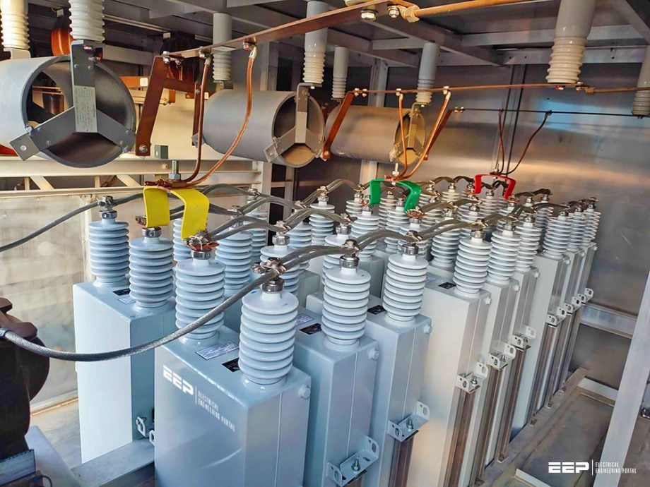
Let’s discuss capacitor banks, but this time, not the basics. Let’s study the double-star capacitor bank configuration and protective techniques used in the substations. How important is to choose the right current transformer ratio, calculate rated and maximum overload currents, and calculate fault MVA % impedance? What about over-voltage protection, transformer ratios, pickup levels, trip delays, and reset delays?
 Capacitor banks in substations: Schemes, relay settings, and protective measures
We will give answers to all the above questions and deepen the discussion even more, but first, for the sake of our young engineers, let’s say a word or two about capacitor banks in general.
Capacitor banks play a pivotal role in substations, serving the dual purpose of enhancing the power factor of the system and mitigating harmonics, which ultimately yields a cascade of advantages. Primarily, by improving the power factor, capacitor banks contribute to a host of operational efficiencies.
The consequential improvement in power quality is accompanied by a decrease in electricity costs, aligning with the broader goals of energy efficiency. Additionally, capacitor banks function as harmonic filters, addressing and minimizing harmonic distortions in the electrical system.
Their presence also contributes to enhancing the short circuit MVA, reducing voltage dips during faults and bolstering the overall resilience of the power infrastructure. Beyond local benefits, capacitor banks play a crucial role in providing reactive power to high-voltage direct current (HVDC) substations, further optimizing their functionality. Moreover, by improving voltages on connected transmission lines and aligning voltages within delta V when connecting two lines, capacitor banks ensure a seamless and stable transmission network.
In essence, the deployment of capacitor banks in substations transcends mere power factor correction, encompassing a spectrum of advantages
that collectively optimize the efficiency, reliability, and quality of the electrical power system.
As the narrative progresses, attention is directed toward the relay and metering single-line diagram of the capacitor bank feeder, offering a high-level overview of the protection and metering circuits. Technical specifications of the 11kV capacitor unit take center stage, spotlighting its impressive impregnation features and surge arrestor implementation.
Moreover, the protection settings for the capacitor bank unfold systematically, elucidating the process of selecting the current transformer ratio, calculating rated and maximum overload currents, and determining the percentage impedance for fault MVA calculations.
Conclusively, the article extends into the realm of overvoltage protection, unraveling the intricacies of potential transformer ratios, pickup levels, trip delays, and reset delays. Each facet is meticulously examined, offering a comprehensive understanding of the capacitor bank’s protective measures.
Throughout this in-depth guide, the interplay between regulatory compliance, cost-effective solutions, and equipment capabilities emerges as a recurring theme, providing valuable insights for engineers, technicians, and stakeholders engaged in optimizing power stability within industrial settings.
- Optimizing Power Factor: Case Study of a Cost-Effective Approach in a 132/11kV Substation
- Double Star Configuration and Protection Strategies for Substation Capacitor Banks
- Operation of Neutral Overcurrent Differential Protection in Double Star Configured Capacitor Banks
- Relay and Metering Single Line Diagram of Capacitor Bank Feeder
- Technical Specifications of 11 kV Capacitor Unit with Impressive Impregnation and Surge Arrestor Features
- 11kV Outgoing Feeder Capacitor Bank Protection Settings
- BONUS! Power factor correction capacitors: Theory & applications (PDF)
1. Optimizing Power Factor
Case Study of a Cost-Effective Approach in a 132/11kV Substation
In this section, we delve into a practical case study involving the selection and calculation of a capacitor bank situated within a 132 by 11 KV substation. The primary objective of this capacitor bank is to enhance the power factor of a factory. Local regulatory standards dictate that the power factor for bulk supply connections must be maintained at 0.9 or higher.
The uniqueness of this scenario lies in the decision to install the capacitor bank at the 11 KV voltage level, even though the factory receives power from the grid at a higher voltage level of 132kV, with an approved connection capacity of 12 megawatts. While the possibility of installing the capacitor bank at the 132kV voltage level exists, this option was deemed cost-prohibitive.
Additionally, the practicality of placing the capacitor bank near the load center factored into the decision-making process.
An intriguing aspect of the power factor optimization strategy employed in this setup is the presence of variable frequency drives. These drives, responsible for controlling the speed of motors, possess the capability to compensate for reactive power, thereby contributing to power factor improvement.
Consequently, the power factor is actively managed by the variable frequency drives, with the capacitor banks serving as a backup mechanism to fulfill regulatory requirements and ensure consistent power factor compliance. This nuanced approach underscores the dynamic interplay between equipment capabilities, regulatory standards, and cost considerations in the realm of power factor optimization within industrial settings.
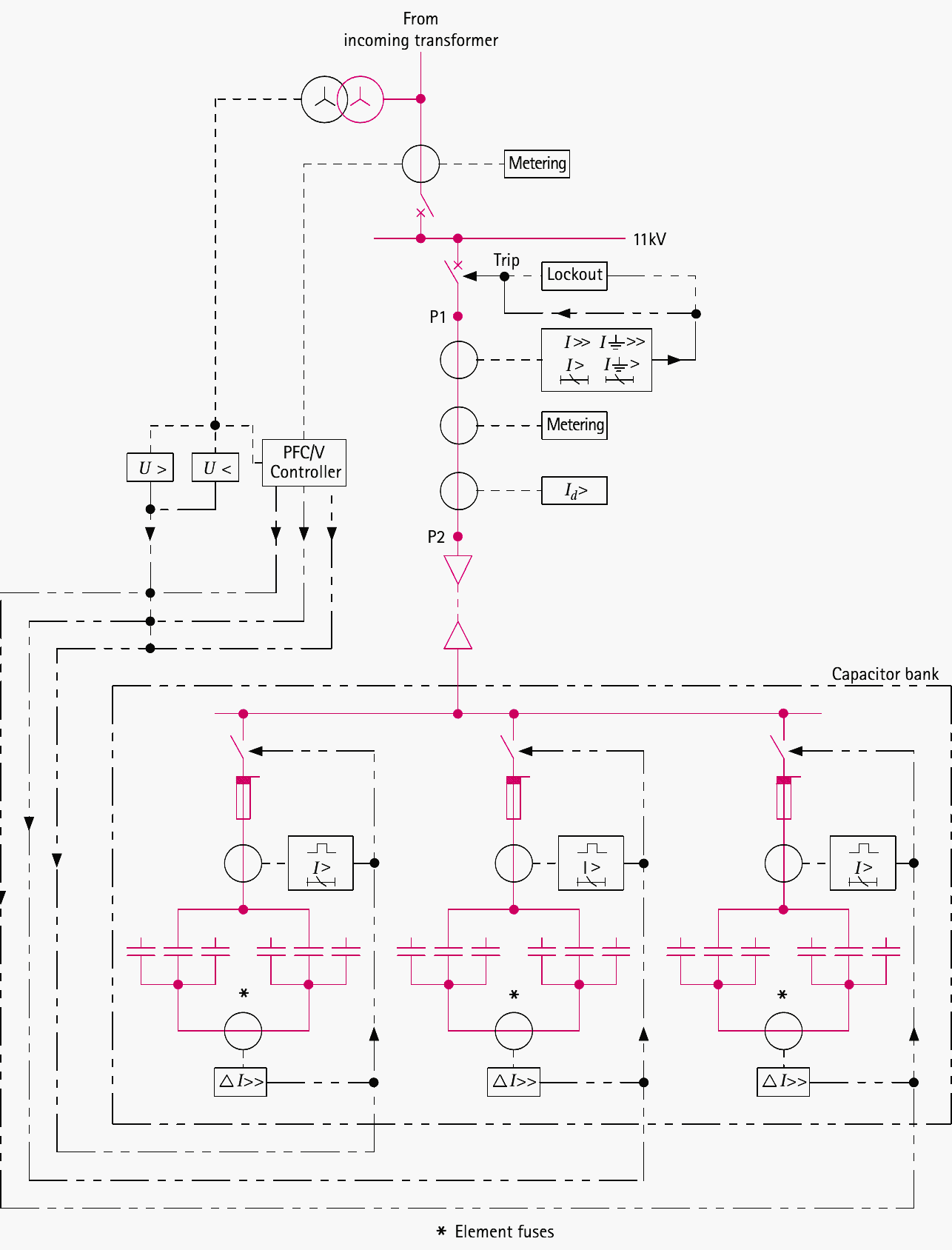
Figure 1 – Scheme of capacitor banks protection
2. Double-Star Configuration and Protection Strategies for Substation Capacitor Banks
The installation of the capacitor bank in the substation adopts a double-star configuration. In this arrangement, capacitors are strategically positioned to create a star connection, and two such double-star-connected capacitor configurations are subsequently connected in parallel.
The configuration of this capacitor bank is visually depicted in Figure 2.
Notably, the chosen protection strategy involves the incorporation of a neutral current transformer positioned between the two star-connected capacitor banks. An additional distinctive feature is the intentional decision not to ground the star point of these capacitor banks.
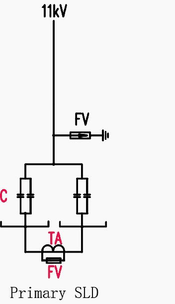
Moreover, surge arrestor protection is implemented for the capacitors, as illustrated in Figure 3, which depicts the single-line diagram of the capacitor bank. Three surge arrestors are installed, with one safeguarding each phase.
Figure 2 – Double Star Connection: Illustration of Capacitor Bank Configuration
Figure 3 – Primary single line diagram of the capacitor bank in the substation
3. Understanding the Operation of Neutral Overcurrent Differential Protection in Double-Star Configured Capacitor Banks
Referring to Figure 2, the capacitors are configured in a Star connection, constituting a double star configuration wherein two star-connected capacitor banks are linked in parallel. Under normal operating conditions, when the capacitor banks are in good health, each phase draws an equal current in the star-connected capacitor bank, resulting in a nearly zero or negligible vector sum of three-phase currents.
Consequently, in a healthy state, there is minimal or no current passing through the neutral current transformer positioned between the star points of the two capacitor banks.
Related electrical guides & articles


Muhammad Kashif
Muhammad Kashif Shamshad is an Electrical Engineer and has more than 17 years of experience in operation & maintenance, erection, testing project management, consultancy, supervision, and commissioning of Power Plant, GIS, and AIS high voltage substations ranging up to 500 kV HVAC & ±660kV HVDC more than ten years experience is with Siemens Saudi Arabia.Profile: Muhammad Kashif
