
Estimated Study Time: 6 minutes
How to improve the power factor?
It’s quite simple. By installing capacitors or capacitor banks. Improving the power factor of an electrical installation consists of giving it the means to “produce” a certain proportion of the reactive energy it consumes itself.
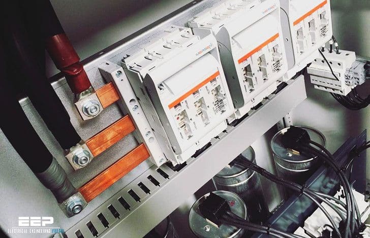 How capacitors improve the power factor and how to calculate them? (photo credit: johnsonphillips.co.uk)
The capacitor is most frequently used, given:
- Its non-consumption of active energy
- Its purchase cost
- Its ease of use
- Its service life (approximately 10 years)
- Its low maintenance (static device)
Power diagram
Power factor is the ratio of working power to apparent power. It measures how effectively electrical power is being used.
To determine power factor (PF), divide working power (kW) by apparent power (kVA). In a linear or sinusoidal system, the result is also referred to as the cosine θ.
PF = kW / kVA = cosine θ kVA
For example, if you had a boring mill that was operating at 100 kW and the apparent power consumed was 125 kVA, you would divide 100 by 125 and come up with a power factor of 0.80.
(kW) 100 / (kVA) 125 = (PF ) 0.80
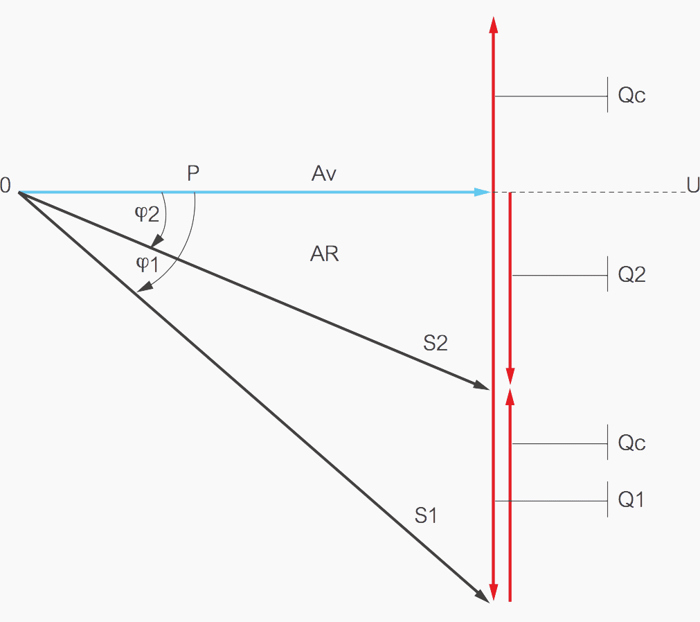
Where:
- P – Active power
- S1 and S2 – apparent powers
(before and after compensation) - Qc – capacitor reactive power
- Q1 – reactive power without capacitor Q2: reactive power with capacitor
Equations:
- Q2 = Q1 – Qc
- Qc = Q1 – Q2
- Qc = P×tg φ1 – P×tgφ2
- Qc = P×(tg φ1 – tg φ2)
Where φ1 is phase shift without capacitor and φ2 is phase shift with capacitor
The capacitor is a receiver composed of two conductive parts (electrodes) separated by an insulator. When this receiver is subjected to a sinusoidal voltage, the current and therefore its power (capacitive reactive) is leading the voltage by 90°.
Conversely, for all other receivers (motors, transformers, etc.) the current and therefore its power (reactive inductive) is lagging the voltage by 90°.
In simple terms, it is said that inductive receivers (motors, transformers, etc.) consume reactive energy whereas capacitors (capacitive receivers) produce reactive energy.
How to calculate the power of capacitors
Based on electricity bills to calculate the capacitor banks to be installed, use the following method:
- Select the month in which the bill is highest (kVArh to be billed)
- Assess the number of hours the installation operates each month
- Calculate the capacitor power Qc to be installed
Example for the subscriber //
- Highest reactive energy bill: December Number of kVArh to be billed: 70,000
- Monthly operating times: High-load + peak times = 350 hours
Qc (bank to be installed) = 70,000 / 350 = 200 kVAr
Based on measurements taken on the HV/LV transformer secondary: PkW-cosFI
Example //
An establishment supplied from an 800 KVA HV/LV subscriber station wanting to change the power factor of its installation to:
- Cosφ = 0.928 (tgφ = 0.4) at the primary
- I.e. Cosφ = 0.955 (tgφ = 0.31) at the secondary, with the following readings:
- Voltage: 400 V 3-phase 50 HZ
- PkW = 475
- Cos (secondary) = 0.75 (i.e. tg ø = 0.88)
Qc (bank to be installed) = PkW x (tgφ measured – tgφ to be obtained)
Qc = 475 x (0.88 – 0.31) = 270 kVAr
Calculation for future installations:
Example
1000 kva transformer, Q capacitor = 250 kVAr
Note: This type of ratio corresponds to the following operating conditions:
- 1000 kVA transformer
- Actual transformer load = 75%
- Cosφ of the load = 0.80 } k = 0.421
- Cosφ to be obtained = 0.95 } – see table below
Qc = 1000 x 75% x 0.80 x 0.421 = 250 kVAr
Capacitor power calculation table
Conversion table
Based on the power of a receiver in kW, this table can be used to calculate the power of the capacitors to change from an initial power factor to a required power factor. It also gives the equivalence between cos ø and tg ø.
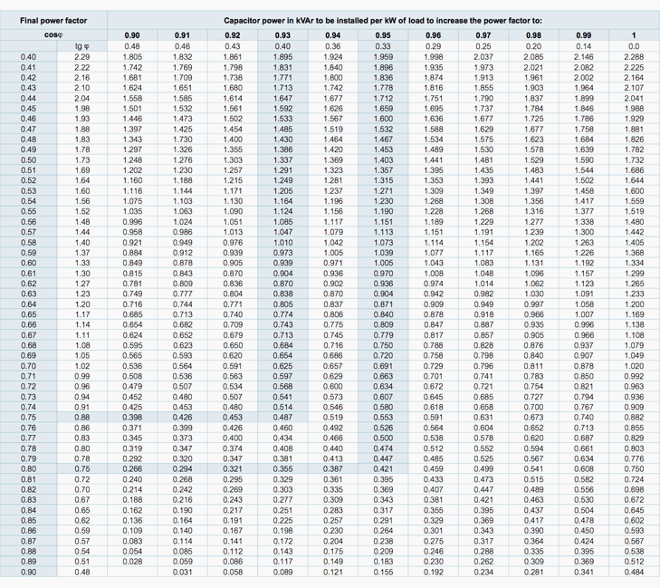
Example: 200 kW motor – cosφ = 0.75 – required cosφ = 0.93 – Qc = 200 x 0.487 = 98 kVAr
Reference // Reactive energy compensation and power quality monitoring by Legrand
Related electrical guides & articles


Edvard Csanyi
Hi, I'm an electrical engineer, programmer and founder of EEP - Electrical Engineering Portal. I worked twelve years at Schneider Electric in the position of technical support for low- and medium-voltage projects and the design of busbar trunking systems.I'm highly specialized in the design of LV/MV switchgear and low-voltage, high-power busbar trunking (<6300A) in substations, commercial buildings and industry facilities. I'm also a professional in AutoCAD programming.
Profile: Edvard Csanyi

Nice
Many years ago I did an Mech and Elec apprenticeship, where I learnt about Power Factor improvements and Voltage management on industrial systems.
Alas, that was a long time ago,
Now, wanting to save pension money on my electric bills at home. I would appreciate some help on where to get advice on using today’s technology to do the similar efficiencies.
Be very grateful for your input, Thanks.
Best wishes,
Peter
NICE
A very useful article
Thanks
Eng sirelkhatim
very good
nice
Very easy to understand. I really enjoy this article. Thanks a lot
Good effort.
Well explained.
Very good and informative keep it up
dentro de su explicación es muy importante para la formación de los futuros ingenieros electromecánicos y los electricistas , hay otra forma practica para resolver la compensación reactiva capacitiva.
por medio de inyección de reactivos con un banco de cualquier capacidad por ejemplo si tenemos 40 kvar los multiplicamos x 24 horas de funcionamiento esto nos da 960 kvarh diarios y los multiplicamos x 30 días de funcionamiento obtenemos 28800 kvarh inyectados al sistema eléctrico de la factoría estos se los restamos a los consumidos en un mes kvarh consumidos- los kavrh inyectados con el banco instalados y la división kvarh totales/kwh nos da el arc tg kvarh totales/ kwh totales y a este resultado del Angulo y se saca el fp mejorado
Pretty good
Nice Information. Well we can make excel sheet for this to calculate require capacitors for power factor improvement.
Thanks for sharing
Interesting, informative and well presented.
useful information
Estoy copiando los temas que ha dejado el Ingeniero Edvard Scesanyi y lo que puedo decir es que se trata de una muy valiosa información, muchas gracias
it is very good information
Well presented! tank you so much…
thank you so much
This information I readout in this your article is of great importance to my electrical power practices. Thank you and please do not hesitate to assist me when I need your help. God bless..
Clear and very illustrative this post.