
Estimated Study Time: 40 minutes
The Art of a Switchyard Design
This technical article describes detailed planning and design phases of a new 220 kV Gas-Insulated Switchyard (GIS) in a 450 megawatt (MW) coal-fired combined heat and power plant (CHP) that was being considered for Ulaanbataar, Mongolia. The project is assumed to have been abandoned or canceled due to public opposition brought on by Ulaanbaatar’s poor air quality. Too bad, because no renewable energy project can actually replace this one.
 A case study of a new 220 kV Gas-Insulated Switchyard (GIS) design for a generation plant
However, the subject of this article is a 220 kV Gas-Insulated Switchyard (GIS), its layout, specification, busbar configuration, cost and finally its interconnections with generation plant.
- Introduction to 220 kV GIS Switchyard
- Decisions Taken
- Observations Concerning 220kV Switchyard Design
1. Introduction to 220 kV GIS Switchyard
To evacuate power from a new thermal power plant, a small 220 kV GIS switchyard is needed. A building with dimensions of 130 x 66 meters will house GIS switchgear with a 245 kV rating. The structure will stand next to the thermal power plant in a designated switchyard area. The design of the GIS switchgear will include a double busbar with eight feeder bays, two bus sections, two bus couplers, and four transformer bays (the thermal generator transformers will be located within the thermal power plant).
The 220 kV switchyard will have SCADA monitoring hardware. It’s important to note that the operation of GIS switchgear will require a number of accessories.
Figure 1 – Main components of CHP generation plant
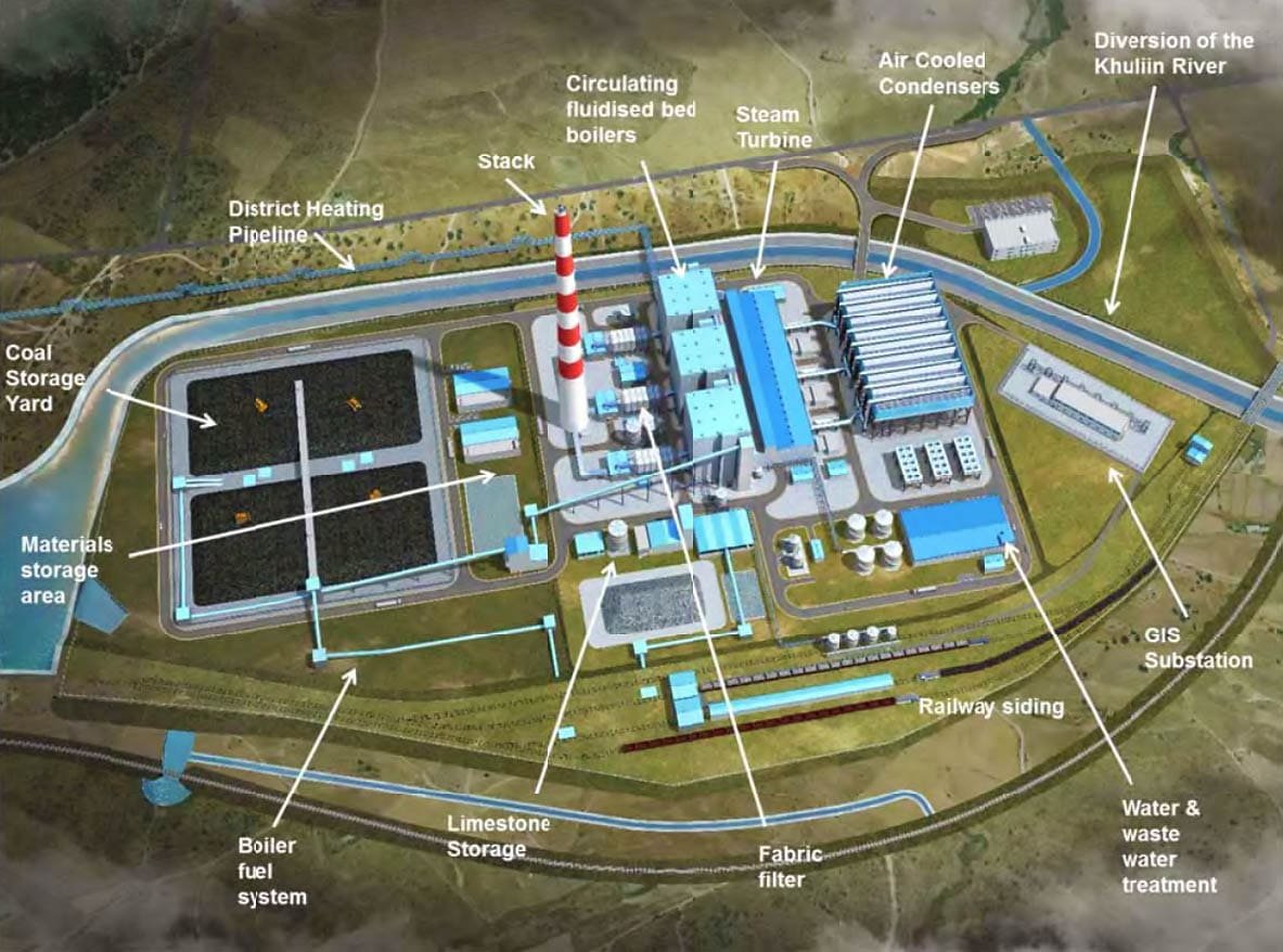
Figure 2 – 220 kV GIS Area (130 m x 66 m)
Figure 3 – 220 kV GIS Area Zoomed
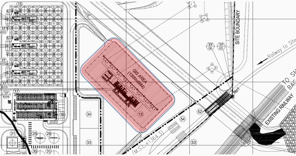
Figure 4 – 220 kV GIS Building Layout
The 220kV GIS switchyard only needs a small footprint, as shown in the site layout figures above, and its small size allows it to overcome any land restriction or limitation problems. Additionally, the environment resistivity is high because all GIS will be housed in a substation building and be enclosed by a grounded metal case.
The 220kV GIS can operate more effectively in the worst environmental conditions, such as a minimum temperature of -50 °C in Mongolia, when compared to the 220kV AIS switchyard, which requires a much higher area and is always located outside to provide better ventilation.
Ok, let’s get to the essential decisions that must have been made in order to continue with the project.
Go back to the Contents Table ↑
2. Decisions Taken
Decision #1 – GIS or AIS
Gas Insulation Switchgear or Air Insulated Switchgear?
Let’s remind ourselves of the basics in a few sentences. Substation is a component of the electrical grid constructed to serve as a connection between generating units and distribution and transmission networks. Switchgear is a crucial part of the substation’s load switching or fault-breaking infrastructure. In our case, conventional Air Insulated Switchgear (AIS) and Gas Insulated Switchgear (GIS) are taken into consideration when analyzing the options for the switchgear to be used at 220kV switchyard connected with thermal power plant.
Due to its small size and electrical safety design, GIS can be located close to the generation and load centers. The shortest possible underground cable could be used to connect the generation facility to the GIS substation.
An example of GIS and AIS footprints comparison and detail comparison study between the two switchgear types and other details GIS and AIS comparison study are as follows:
Figure 5 – Example of GIS and AIS footprints comparison
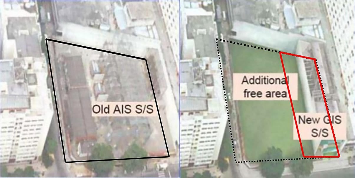
As a result, the plant’s electrical transmission efficiency to the GIS substation will be significantly higher. Because the GIS panels are grounded at the metal enclosure, operating a GIS is safer than operating an AIS. Additionally, the strength of the SF6 insulation means that the electric arc produced when the mechanism is switched from closed to open is much smaller.
The GIS is typically housed in the substation building, where all operations can be carried out even in unfavorable weather conditions. However, factors such as humidity, environmental concerns like rain, storms, and pollutants will have an impact on the level of air insulation. In the winter or under other unfavorable conditions, the operation period will also be shortened.
The total enclosed GIS switching mechanism can be resisted insulation deterioration against the environment and result maintenance free and operating check-up as minimum.
The initial capital expenditure for the substation includes the cost of the equipment as well as any associated civil and electrical system interface costs, like cable costs. Despite having more expensive equipment than AIS, GIS requires less space to operate and requires less concrete to load its equipment, which results in lower civil construction costs.
Additionally, GIS only needs shorter cables to connect to the generation plant, so using GIS will definitely result in lower costs for the interface components like cables.
Suggested Reading – GIS AC/DC auxiliary circuits and circuit breaker closing circuit
Mastering GIS control circuits: AC/DC auxiliary circuits and circuit breaker closing circuit
When that happens, the GIS substation’s total capital cost will be comparable to the AIS substation’s. In the meantime, a significant issue for long-term consideration is the cost of operating the substation. The GIS has lower operational costs than the AIS type because the switching mechanism is maintenance-free and there are fewer operating inspections required.
Low fault rates and higher reliability will reduce the long-term operational costs of GIS. The fault rate is influenced by grid reliability, which includes the fault rate across the entire network, the maximum fault level, and environmental factors.
So, the adoption of GIS is recommended to provide a high reliability and efficient switching and protection way in connection with the new coal-fired combined heat and power plant and the new/existing power lines after taking into account the safety, technical, environmental, financial, and economical factors between the GIS and AIS. GIS substation has advantage of compact size which only 1of 10 times when comparing with AIS substation.
Following table is summarized the comparison between GIS and AIS:
Table 1 – Comparison between GIS and AIS
| Comparison of: | GIS | AIS |
| Size | 10% of AIS | 10 times of GIS |
| Dielectric clearance | Superior | Normal |
| Modular assembly | Yes | No |
| Maintenance | Free | Periodic |
| Fault related outage | Lower | Higher |
| Gas monitoring | Yes | No |
| Environment resistivity | Higher | Lower |
The major components of GIS are shown in following figure below.
Each compartment of the GIS is filled with SF6 gas that provides as insulation and results superior dielectric clearance and compact switchgear size. The high reliability of GIS will minimize fault outage time and support maintenance free.
However, as the filled SF6 gas pressure to maintain the electrical insulation; the pressure is continuously monitored by gauges and the signal will not only be read on site, but also sent out to SCADA system for record and remote supervision.
Figure 6 – Gas-insulated switchgear structure and components

Go back to the Contents Table ↑
Decision #2 – Busbar Configuration and Design
The choice of busbar configuration is another crucial factor in the design of the switchyard. Following is a discussion of various busbar configurations, including single busbar, double busbar with or without transfer busbar, and one and a half busbar:
1. Single Busbar
A single busbar configuration is the simplest and least expensive design. However, any busbar maintenance or fault will result in a complete substation switchout. Additionally, any circuit breaker failure on a line or transformer necessitates the shutdown of the load on that line or transformer.
Distribution substations up to 35 kV use this configuration, but transmission substations with higher voltage levels and capacity demands, like the new 220 kV switchyard applicable, are not suitable for it.
Figure 7 – Single Busbar arrangement
Figure 8 – Switchgear bay with a single busbar arrangement
Go back to the Contents Table ↑
2. Double Busbar
This type of busbar configuration is a high flexibility one that half the feeder circuits are being connected to each busbar. Bus-coupler is required for the normal operation and any feeder circuit can be transfer to any busbar.
The disadvantage of this type is that outage on the circuit breaker of the feeders will require shut-down of the whole feeder and failure of protection scheme may cause loss of substation supply.
Related electrical guides & articles


Edvard Csanyi
Hi, I'm an electrical engineer, programmer and founder of EEP - Electrical Engineering Portal. I worked twelve years at Schneider Electric in the position of technical support for low- and medium-voltage projects and the design of busbar trunking systems.I'm highly specialized in the design of LV/MV switchgear and low-voltage, high-power busbar trunking (<6300A) in substations, commercial buildings and industry facilities. I'm also a professional in AutoCAD programming.
Profile: Edvard Csanyi
