
Estimated Study Time: 4 minutes
The problem – steel mill with variable speed drives
A steel mill with variable speed drives (VSDs) had problems of frequent tripping of the VSDs with the indication overvoltage in AC line. Each tripping caused severe production disruption and resulted in considerable monetary loss due to lost production.
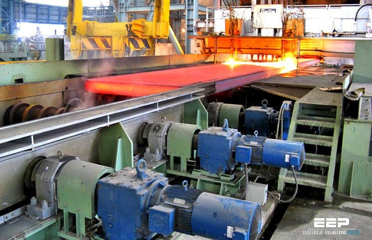
Steady-state measurements by true RMS voltmeter showed that voltage was normal and within the specified operating range of the VDS. A power line monitor was then used in the distribution board feeding the VSDs and the incoming power feeder to the mill. At both locations, the monitors showed transient overvoltages of damped oscillatory type waveform with an initial amplitude of over 2.0 pu and a ringing frequency of about 700 Hz.
The timing of disturbances coincided with the closing of capacitor banks in the utility substation feeding the steel mill (refer Figure 1a below).
Analysis
It was confirmed by the VSD manufacturer that the VSDs were provided with overvoltage protection set to operate at 1.6 pu voltage for disturbances exceeding 40 µs.
It may be noted that switching on a bank of capacitors results in high charging current inrush. When this current passes through the line’s inductance L, a momentary voltage surge occurs. Further interaction of the capacitor C with inductance L results in an oscillatory flow of current, which is damped by the resistance R in the system.
The oscillatory disturbance superimposed over the normal power-frequency voltage wave caused the overvoltage protection to operate.
Solution
The solution lies in reducing the transient peak to a value that is below the overvoltage protection threshold.
This was achieved in this case by installing a surge protection device (SPD) in each VSD. The SPD clamped the transient to a peak value of 1.5 pu thus avoiding the operation of overvoltage protection.
Another possible solution would have been to install an inductor L1 in the switching circuit of the capacitor for a few seconds and then shunt it by switch S.
Since the voltage seen by the incoming feeder to the mill would be the combination across C and L1, the transient will have a smaller amplitude. This solution will however call for cooperation from the utility as it involves additional equipment to be installed by them (refer Figure 1b above).
Reference: Practical Grounding, Bonding, Shielding and Surge Protection – G. Vijayaraghavan, Mark Brown and Malcolm Barnes (Get your harcopy from Amazon)
Related electrical guides & articles


Edvard Csanyi
Hi, I'm an electrical engineer, programmer and founder of EEP - Electrical Engineering Portal. I worked twelve years at Schneider Electric in the position of technical support for low- and medium-voltage projects and the design of busbar trunking systems.I'm highly specialized in the design of LV/MV switchgear and low-voltage, high-power busbar trunking (<6300A) in substations, commercial buildings and industry facilities. I'm also a professional in AutoCAD programming.
Profile: Edvard Csanyi

We have seen that the standard methodology of inserting varistors or GDT’s into the system are not adequate to give significant reduction of the transient related issues. A device that is designed to respond specifically to ringing transients provides significantly better reduction of these types of events and related false zero crossings of the sinewave (generated by the VSD) that negatively impact PLC’s.
Thank you for the much needed articles , the information sheds light on the energy saving initiatives we are venturing in our region here in the Bahamas. Keep it sweet and simple.