
Estimated Study Time: 14 minutes
Equipment temperature monitoring
The pilot project of installation the temperature monitoring system (researched, developed and manufactured by VTI) deployed at critical substations on the power system managed and operated by Vinh Phuc Power Company (a member of Northern Power Corporation – EVNNPC) in November 2023.
 A Case Study of Overheating Substation Electrical Equipment and Temperature Monitoring Solution
After installation, the monitoring system issued overheating warnings on electrical equipment; helps the operations management promptly detect problems and take action to prevent them from developing into serious failures.
- Description of temperature monitoring system:
- The parameters monitored by the system:
- Evaluation the quality, stability, advantages and disadvantages of the system:
- Results of temperature monitoring during the pilot phase:
- Conclusion
- BONUS (PDF) 🔗 Download ‘The Design Basics for Medium-Voltage Switchgear and Networks’
1. Description of temperature monitoring system
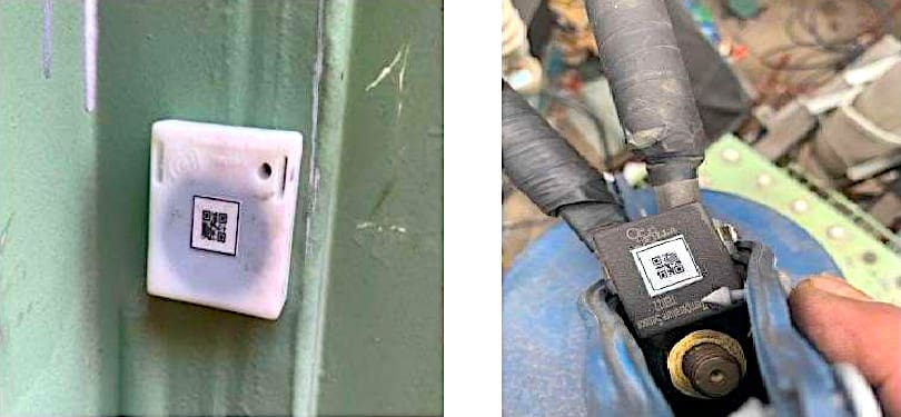
Consisting of wireless temperature sensors and camera
1.1 At 110kV Hoi Hop substation
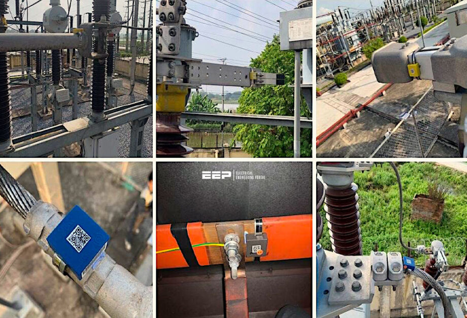
Installing wireless sensors at locations: CT172, DS172-2, DS112-2, DS132-2, CB132, CT132, DS132-3, cabinet VT C32, DS T302-2, CB T302, CT T302. Installing fixed thermal cameras for comprehensive monitoring of T2 power transformer.
Figure 1 – Installed wireless sensors
1.2 At 22/0,4kV Ao Hai substation:
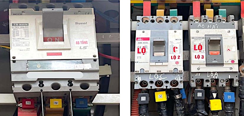
Installing wireless sensors at the high and low voltage bushing terminal of the power transformer, power transformer tank, main MCCB and 02 branch MCCBs.
Installing each phase current transformer for the main MCCB and branch MCCB 4 & 5 to measure operating parameters.
Figure 2 – Installed wireless sensors on LV circuit breakers
2. The parameters monitored by the system
2.1 Monitoring parameters
2.1.1 110kV Hoi Hop substation:
- T2 power transformer: HV, MV, LV bushing terminal contact temperatures of the power transformer; Temperature of HV, MV, LV bushing of power transformer; Top oil temperature through the power transformer main tank; Power transformer main tank temperature; Auxiliary oil tank temperature.
- 110kV DS: Temperature of the contact position; Temperature of the bushing terminals
- 110kV CB: Temperature of the bushing terminals at both sides of the CB
- 110kV CT: Temperature of the bushing terminals (03 phases)
- Surge arrester on MV, LV side of power transformer: Temperature of the bushing terminals; Temperature of the SA.
- VT panel of C32 busbar: Temperature of 03 phases C32 busbar; Ambient temperature and humidity in the VT panel of C32 busbar.
- Power cable: Temperature of power cable terminals at MV, LV sides of T2 power transformer.
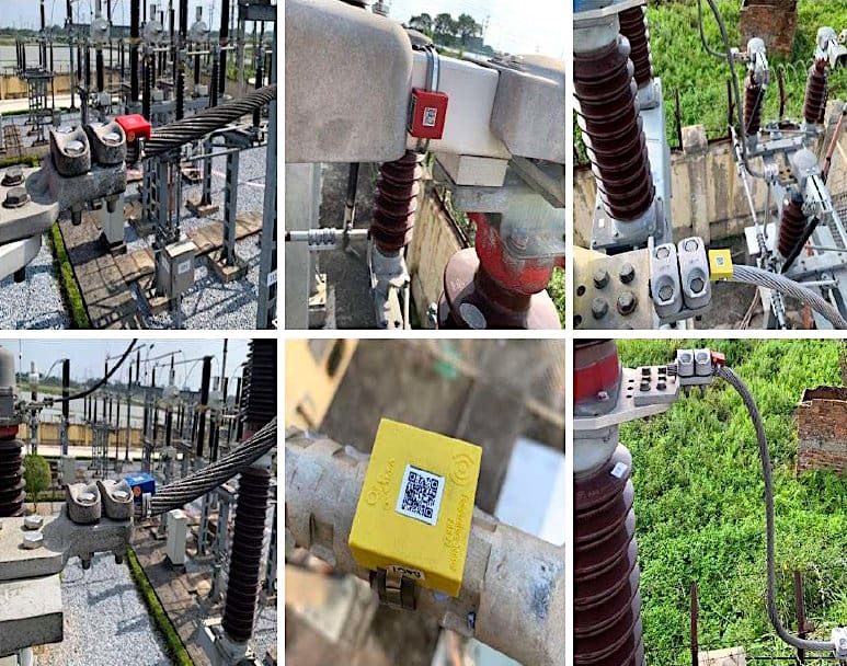
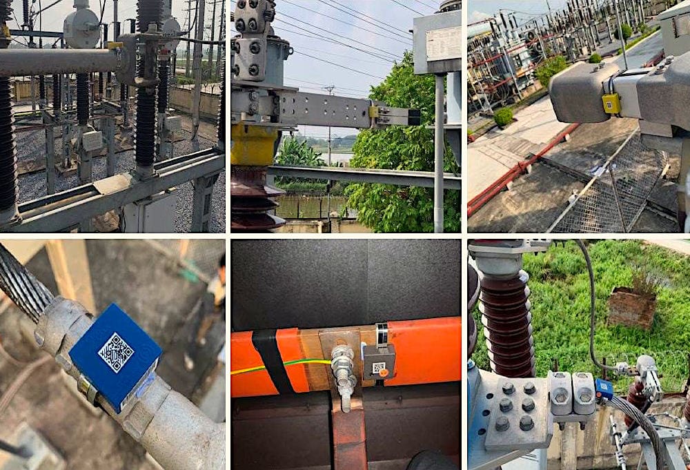
Figure 3 – Installed wireless sensors in 110kV substation
2.1.2 22kV Ao Hai substation:
- Temperature monitoring: HV, LV bushing terminal contact temperatures of the power transformer; Top oil temperature through the power transformer main tank; Temperature of the LV panel, contact terminal of main MCCB and branch MCCBs.
- Ambient temperature.
- Monitoring of operation parameters of main MCCB and branch MCCBs: Current (I), voltage (U), power (P, Q, S), power factor (PF), frequency (f), power energy (A).
Figure 4 – Wireless sensors installed on HV, MV, LV bushing of power transformer, and on power transformer main tank
2.2 Warning parameters
- Overheat warning: optional setting the comparison with absolute value or comparison between phases or comparison between phases with ambient temperature
- Warning of operating parameters: Overload/underload of main MCCB and branch MCCBs; Over/under voltage; Phase unbalance warning shows whether phase balance is needed or not; Low power factor of main MCCB and branch MCCBs
3. Evaluation the quality, stability, advantages and disadvantages of the system:
3.1 Quality and stability of the system
- Temperature data at points on the power transformer; others primary equipment collected to mobile applications relatively accurately and stable. The data was checked with a handheld thermal camera within the error range (0,4 °C-3,2 °C).
- Temperature and humidity data of MV panel collected to the mobile device application is relatively accurate and stable.
- Operating parameter data of main MCCB and branch MCCBs collected to mobile device application are relatively accurate and stable. The data is checked against the operating parameters of the total station energy meter and current clamp meter.
Recommended Guide – Automated system monitoring of MV/HV circuit breakers (condition, status and operation)
Automated system monitoring of MV/HV circuit breakers (condition, status and operation)
3.2 Advantages and disadvantages of the system
3.2.1 Advantages:
- Ability of continuously monitor equipment in the substation (temperature, humidity, operating parameters). There is no limit to the number of heat points and locations that need to be monitored.
- Wireless sensors are easy to install. Installed sensors do not interfere with internal power transformers and other electrical equipment.
- The monitoring system can be displayed on both the web interface and mobile application (ios/android).Through testing, the application operates stably, the interface is clear, easy to use, and no errors have appeared.
- Compared to systems using wired sensors: Minimizes the risk of mouse bites, short circuits and increases aesthetics.
- Instant warnings of abnormal thermal and electrical phenomena, event messages are sent immediately via application on mobile devices.
- Reduce labor costs, reduce safety risks for operators when they do not have to come into direct contact or get close to electrical components.
- Detect overheating points in medium voltage switchgear and medium voltage equipment where the contact terminals have been insulated with silicone (5S electrical grid) that traditional temperature testing devices cannot check.
- Monitoring data can be stored.
Good Reading – The true art of control, monitoring and protection provided by Substation Automation Systems
The true art of control, monitoring and protection provided by Substation Automation Systems
3.2.2 Disadvantages:
- When installing or repairing wireless monitoring sensors, the power of the device with the sensor attached must be cut off to be able to do the task.
- The current transformer to monitor operating parameters for each phase of the 400V feeder is still bulky and not suitable for the 400V cabinet panel space (a number of current transformers must be installed outside the cabinet).
- Wireless transmission ability depends on the stability of the 3G/4G SIM card or the wifi network system at the station. In fact, during testing, the device occasionally reported a connection loss error.
4. Results of temperature monitoring during the pilot phase
4.1 Overheating detection on 110kV HV bushing terminal of T2 power transformer at 110kV Hoi Hop substation
T2 power transformer 115/38,5/23kV – 63MVA in 110kV Hội Hợp substation was made by Cam Pha Electrical Equipment Joint Stock Company (VEE) in 2016. After installing the thermal monitoring system, during peak hours of the day, the monitored temperature at the bushing terminals of phase A and phase C of T2 power transformer increased, and a deviation warning appeared (delta) temperature of bushing terminals A and C with bushing terminal B on the 110kV side.
Thermal images and temperature data are displayed directly on the monitoring interface.
Figure 5 – Images of phase A and phase C bushing terminals on the 110kV side show overheating on the thermal image background
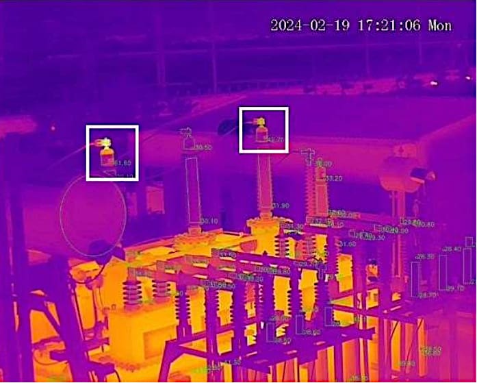
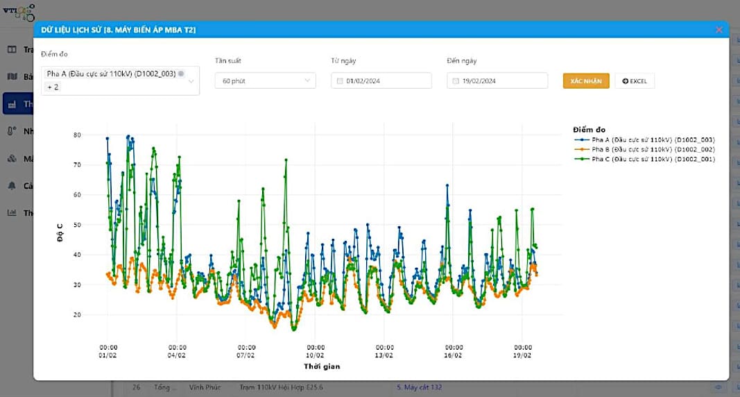
Figure 6 – Overheating diagram of phase A and phase C bushing terminals of 110kV T2 power transformer
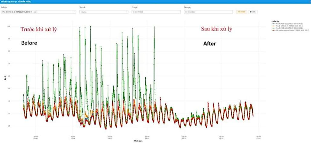
4.2 Overheating detection on terminal of phase C of branch MCCB 2 at 22/0,4kV Ao Hai substation
After installing the thermal monitoring system, the branch MCCB 2 monitoring temperature increased abnormally at phase C, details as following:
21/11/2023: Vinh Phuc Power Company and VTI technical staff came to the substation to check and verify the results. After measuring, confirming that VTI’s temperature monitoring system reports correctly, there is overheating at the location as warned on the software.
Figure 7 – Feeder 2, phase C (The second MCCB from the left is overheated)
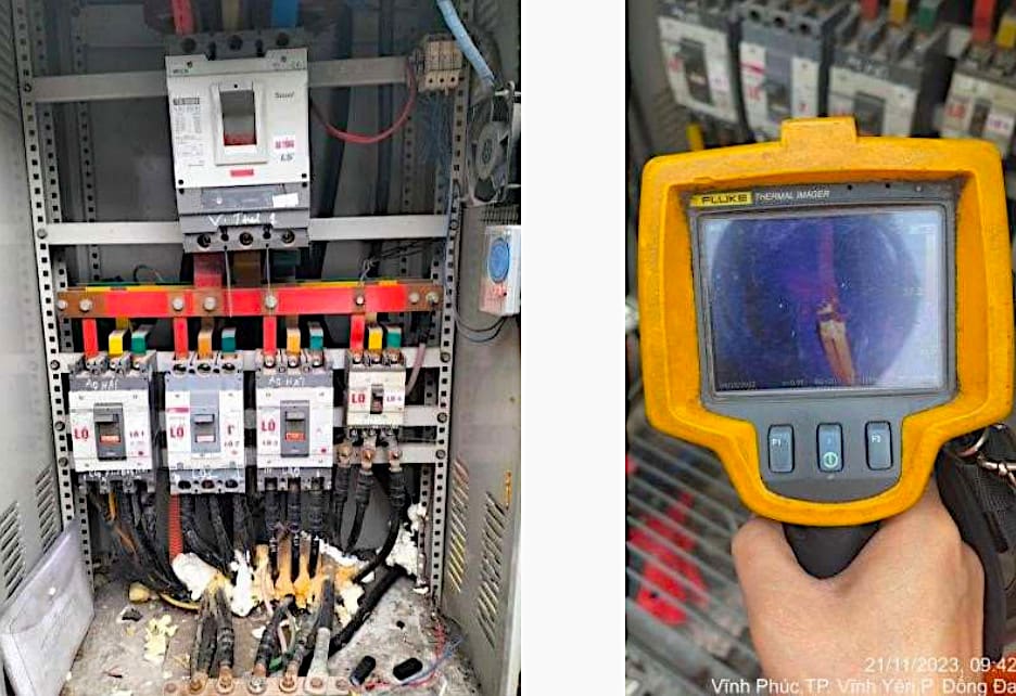
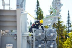
On November 27, 2023, Vinh Yen city power branch cut off the power, reprocessed the contact points, and re-pressed the terminals. After treatment, the temperature of phase C of MCCB branch 2 returned to normal.
Figure 8 – Vinh Yen city power branch cut off the power
4.3 Verification of monitoring results at 110kV Hoi Hop substation
January 9, 2024: Technical Department of Northern Power Corporation together with Vinh Phuc Power Company and technical staff of VTI company came to the substation to experiment, check, measure and verify the results.
Use the handheld temperature measuring device of mobile operations team to directly measure the temperature at monitoring points and compare with monitoring results at the same time. The verification results are similar, the deviation is within the range of (0.4÷3.2) °C.
This error may be due to the error of the monitoring sensor itself (±1 °C) and the error of the handheld device.
Table 1 – Measurement results at 110kV Hoi Hop substation
| No. | Measuring point | Temperature °C (hendheld measurement) | Temperature °C (monitored) | Deviation |
| (1) | (2) | (3) | (4) | (5) = (4) − (3) |
| 1 | DS 112-2 phase A | 27.2 | 30.4 | 3.2 |
| 2 | DS 112-2 phase B | 27.9 | 29.6 | 1.7 |
| 3 | DS 112-2 phase C | 27.3 | 28.8 | 1.5 |
| 4 | DS 172-2 phase A | 24.8 | 25.6 | 0.8 |
| 5 | DS 172-2 phase B | 26.9 | 27.3 | 0.4 |
| 6 | DS 172-2 phase C | 28.7 | 30.1 | 1.4 |
| 7 | CT 172 phase A | 28.8 | 30.5 | 1.7 |
| 8 | CT 172 phase B | 28.1 | 30.2 | 2.1 |
| 9 | CT 172 phase C | 28.3 | 30.4 | 2.1 |
| 10 | DS 132-2 phase A | 28.3 | 30.5 | 2.2 |
| 11 | DS 132-2 phase B | 26.5 | 27.9 | 1.4 |
| 12 | DS 132-2 phase C | 25.7 | 28.3 | 2.6 |
| 13 | CT 132 phase A | 27.6 | 29.5 | 1.9 |
| 14 | CT 132 phase B | 27.5 | 28.4 | 0.9 |
| 15 | CT 132 phase C | 27.6 | 28.8 | 1.2 |
| 16 | CB 132 phase A | 27.5 | 28.8 | 1.3 |
| 17 | CB 132 phase B | 27.4 | 28.3 | 0.9 |
| 18 | CB 132 phase C | 27.2 | 29.5 | 2.3 |
| 19 | DS 132-3 phase A | 27.3 | 28.5 | 1.2 |
| 20 | DS 132-3 phase B | 27.0 | 28.3 | 1.3 |
| 21 | DS 132-3 phase C | 27.3 | 28.9 | 1.6 |
| 22 | 110kV bushing terminal phase A of T2 | 35.1 | 35.1 | 0 |
| 23 | 110kV bushing terminal phase B of T2 | 27.4 | 30.1 | 2.7 |
| 24 | 110kV bushing terminal phase C of T2 | 36.2 | 35.8 | −0.4 |
| 25 | Neutral 110kV bushing terminal of T2 | 31.5 | 33.5 | 2 |
5. Conclusion
The temperature monitoring system helps the operation management detect overheating on electrical equipment, promptly handle and avoid serious failures that may occur.
This is an important basis to officially widely deploy the installation of the temperature monitoring system on the Northern Vietnam power system.
6. Attachment (PDF): The Design Basics for Medium-Voltage Switchgear and Networks
Download: The Design Basics for Medium-Voltage Switchgear and Networks (for premium members only):
Related electrical guides & articles


Group of Authors
1. Ninh Nguyen Cao Ninh Nguyen is currently the chairman and CEO of VTICorp. He has many years of experience in the healthcare, defense, and energy sectors. He is a pioneer in conceptualizing, researching, developing, and commercializing digital transformation, automation, and IoT solutions. These solutions include: wireless sensor-based temperature and humidity monitoring; line thermal monitoring; AI smoke/fire detection; and energy saving solutions.2. Hung Viet Bui Hung Viet Bui received his Bachelor of Engineering degree in Electronics and Telecommunications from Da Nang University of Technology in 2011 and has nearly 15 years of experience in research and development. He is currently the lead researcher at VTICorp. His areas of expertise include embedded programming, circuit design, artificial intelligence, signal processing, communications, and IoT.
3. Thuc Vu Cong Thuc Vu Cong received his Master's degree in Electrical Engineering from Hiroshima University in 2022. He is currently an applied engineer and project manager at VTICorp. His research areas include testing and diagnostics of electrical equipment, and continuous monitoring solutions.
4. Ba Nguyen Van Ba Nguyen Van is currently the Head of Technology at VTICorp, with over 20 years of experience in the field of information technology. His research areas include System Architecture Design, IoT, DevOps and Automation, and Big Data & Analytics.
5. Anh Tung Tran Anh Tung Tran received Ph.D. degree in Electrical Engineering from Paul Sabatier –Toulouse III University in 2012. He worked as postdoctoral position in Montpellier II university in 2013 and at École Technologie Supérieure (Montreal) in 2016. He is now Associate Professor at Electric Power University in Hanoi, Vietnam. His field of interest includes nanodielectric composites, polymeric insulation material, electrical network optimization and smart grids.
Profile: Group of Authors

Very informative technical article