
Estimated Study Time: 20 minutes
Centralized reactive-power compensation
For energy-efficient operation of decentralized multiply-fed industrial networks, each load-centre substation must have its own centralized reactive-power compensation system for automatic PF correction. The automatic reactive-power compensation systems used for load-related control of the reactive power comprise a PF controller and a power section.
 Operating centralized automatic compensation systems when supplying linear loads (photo credit: ryanwilks.com)
The power section includes:
- Fuse-switch-disconnector and connecting cable,
- Power capacitors without reactors (for linear loads) or with reactors (for non-linear loads) with parallel discharge resistors,
- Contactors for switching the power capacitors,
- Fuses for the capacitor branch circuits.
Figure 1 (see below) shows the schematic diagram of a centralized reactive-power compensation system for automatic PF correction.
Meeting the most important electrical conditions for safe and reliable operation of automatic compensation systems is explained below.

- Selecting a current transformer for the PF controller
- Defining the number of steps and the step power
- Setting the controller sensitivity (C/k response value)
- Requirements, connection and fuse protection of the power capacitors
1. Selecting a current transformer for the PF controller
Connection of a PF controller with a measurement current input of IN2 = 5 A (normal type) or IN2 = 1 A makes installation of a current transformer necessary. The nominal primary current IN1 of the current transformer must be selected according to the maximum load current of the supplying distribution transformer.
The following applies:
Where:
- IN1 – Nominal primary current of the current transformer
- IT-AF – Maximum load current of the transformer with radial-flow fans switched on (AF mode)
- SrT – Rated power of the transformer
- UrT – Rated voltage of the transformer
- kAF – Factor for the overload capability in AF mode (kAF ≤ 1.4)
The following data are relevant to current transformers provided for connecting the PF controller:
- Type of current transformer (e.g. bushing type, core balance or bar-primary type),
- Highest voltage for equipment Um (Um = 660 V or Um = 800 V is usual in the normal version),
- Rated transformation ratio k = IN1/IN2 (e.g. k = 2500 A/5 A = 500),
- Rated power Srb (Srb = 10 VA is generally chosen),
- Accuracy class (classes 1 to 3).
When selecting the current transformer, the sensitivity of the PF controller must also be taken into account. A specific current change ΔI is required to start the control process. For example, a Modl PF controller in conjunction with a 5-A current transformer only initiates control as from a current change of ΔI ≥ 50 mA.
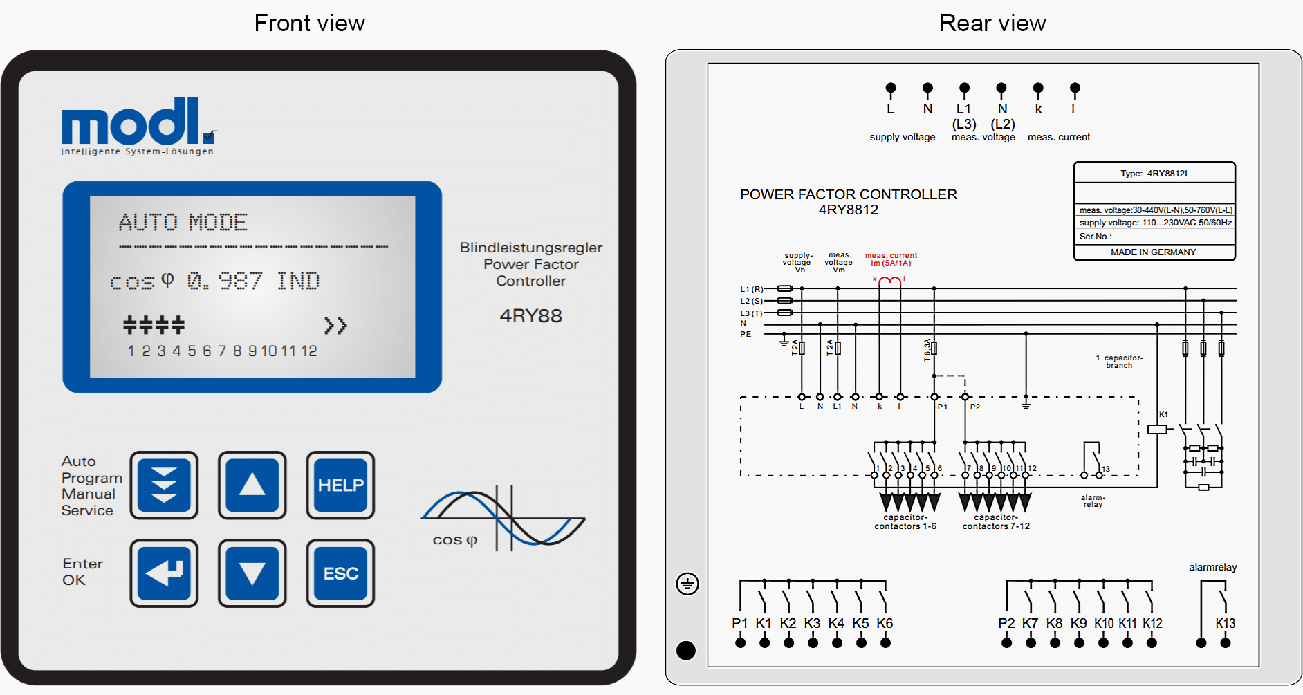
Table 1 (see below) provides information about the current changes ΔI caused in PF controllers when deployed in automatic compensation units with different sizes of current transformer and capacitor step powers.
If an automatic compensation unit is used in 690-V networks, the values from Table 1 must be multiplied by a factor of 0.58 (400 V / 690 V). Only current-transformer step-power combinations are permissible that still ensure a current change of ΔI ≥ 0.050 A after this multiplication.
Correct installation of the current transformer is essential for correct power-factor correction (PFC). Seen in the direction of power flow, the current transformer must always be installed upstream of the branch circuit to the compensation unit (Figure 1). Installation downstream of the branch circuit to the compensation unit would prevent detection of the compensation effect.
2. Defining the number of steps and the step power
To implement a PFC system that is matched to the prevailing network conditions, the necessary total capacitor power must be divided into steps.
The number of steps denotes the ratio of the total compensation power to the smallest switchable capacitor power. Good matching to the required power factor cos φ2 can be achieved with just five switching steps. In decentralized multiply-fed LV networks, no more than three to four capacitor control steps are required for each load-centre substation.
For example, if n = 4 decentralized distribution transformers are supplying the LV network, division of the total capacitor power should be performed in 12 to 16 steps.
Only in industrial plants with a relatively large number of motors and small connected loads might it be convenient to provide more finely stepped PFC.
Experience has shown that, to correct the power factor of cos φ1 = 0.7 to cos φ2 = 0.9…0.95, approximately 40 % of the transformer rating is required as capacitor rating (Qc ≈ 0.4 × SrT). The capacitor step power should be approximately 10 to 20 % of the required capacitor power (Qc-step ≈ (0.1…0.2) × Qc).
The capacitor step power is therefore the smallest switchable capacitor power.
Table 2 shows the arithmetic switching sequence of a 400 kvar PFC unit as a switching step diagram. The equivalent switching step diagram for a mixed step function ratio is illustrated by Table 3.
Today‘s PF controllers are capable of all three step function ratios described. For design and budget reasons, however, intelligent step function ratios that combine the classic step function ratios (e.g. 1:1:2:2:2:4) are used. An “intelligent” controller attempts to switch capacitors of the same power equally frequently.
Table 2 – Switching step diagram (Qc = 400 kvar, arithmetic step function ratio)
Table 3 – Switching step diagram (Qc = 400 kvar, mixed step function ratio)
3. Setting the controller sensitivity (C/k response value)
The PF controller detects the reactive power at the incoming supply by measuring the current and voltage (see Figure 1).
If the reactive power deviates from the set target value, the controller outputs control commands to the capacitor contactors and connects or disconnects them in steps, as required. The PF-controller requires a defined sensitivity value to initiate the control process.
In accordance with this response threshold, the C/k value must be calculated as follows:

Where:
- Qc – Smallest capacitor step power
- UnN – Nominal system voltage
- k – Transformation ratio of the current transformer (k = IN1/IN2)
The C/k response value calculated according to above equation above ensures that temporary load peaks do not result in hunting of the automatic control. Modern controllers also permit non-hunting control by time-delayed connection and disconnection of the capacitor step power.
For centralized compensation of the reactive power, controllers with the following C/k value settings are now available on the market:
- Manual C/k value setting (setting of the PF controller according to the result calculated with above equation),
- Semi-automatic C/k value setting (entry of the transformation ratio k of the current transformer and the smallest capacitor step power Qc),
- Fully automatic C/k value setting.
In PF controllers with fully automatic C/k value setting, it is neither necessary to enter the CT transformation ratio k nor the capacitor step power Qc. The compensation effect achieved by each capacitor is stored and monitored, including the response threshold of 60 to 85 %.
Because of the “intelligence“ of the PF controller, very adaptable reactivepower compensation can be achieved without an invariably predefined switching step program.
4. Requirements, connection and fuse protection of the power capacitors
Power capacitors for improving the power factor cos φ of LV networks must meet the requirements defined in DIN EN 60831-1 or IEC 60831-1. The values specified in Table 4 must be complied with for the electrical strength of the power capacitors for PF correction.
The decisive quantity for the electrical strength of the capacitor is its rated voltage UrC. When selecting the rated voltage UrC, both the nominal system voltage UnN and the reaction of the capacitors on the power system must be taken into account.
Table 4 – Permissible voltage values for operation of power capacitors for PF correction
| Frequency | Voltage (RMS value) | Maximum duration | Remarks |
| System Frequency | 1.00 × UrC | Continuous | Highest average value during any period of capacitor energization |
| 1.10 × UrC | 8h per day | Low-voltage fluctuations | |
| 1.15 × UrC | 30 min per day | ||
| 1.20 × UrC | 5 min | Voltage rise at light load | |
| 1.30 × UrC | 1 min |
UrC – Rated voltage (RMS value of the sinusoidal alternating voltage for which the capacitor has been designed. For polyphase capacitors with internal electrical connections between the phases and for polyphase capacitor banks, refers to the line-to-line voltage.)
In industrial networks, there can be a considerable difference between the nominal system voltage and the rated voltage of the capacitor.
In decentralized multiend-fed networks, capacitors cause the following permanent voltage increase:
Where:
- ΔU – voltage rise in V
- U – voltage before connection of the compensation power installed in the load-centre substation in V
- Sk” – characteristic short-circuit power of the LV network at the decentralized installation locations of the load-centre substations in MVA
- Qci – available compensation power of a decentralized load-centre substation i (i = 1, 2, …, n) in Mvar
- i – Incrementing index for decentralized load-centre substations, i = 1(1)n
- n – number of decentralized load-centre substations
To achieve the full capacitive power with an increased electrical strength of the capacitors, the following calculation must be made:

Where:
- QrC – capacitor rating required for the increased electrical strength in kvar
- Qc – capacitive power required to improve the power factor from cos φ1 to cos φ2
at the nominal system voltage in kvar - UrC – rated capacitor voltage for the increased electrical strength in V
- UnN – nominal system voltage in V
In a 400 V network, for example, according to above equation, dimensioning of a 250 kvar capacitor bank for the increased rated capacitor voltage UrC = 525 V would necessitate installation of a rated power:
QrC = 430 kvar (QrC = 250 kvar (525 V/400 V)2 = 430 kvar).
In addition to the necessary electrical strength, the power capacitors must have a certain safety margin for thermal loads due to the fundamental current and harmonic currents. According to DIN EN 60831-1 or IEC 60831-1, the safety margin is limited to 1.3 × InC in continuous operation with sinusoidal rated voltage. Considering the capacitance tolerance of 1.15 × Cr, the maximum permissible current can have values up to 1.5 × InC.
These maximum values of the current-carrying capacity must not be exceeded during operation of capacitor units either with or without reactors.
The recommendations for dimensioning the connection cables are based on the current-carrying capacity criteria of DIN VDE 0298-4 or IEC 60364-5-52.
Table 5 – Recommended line fuses and connection cables for compensation units without reactors
1) LV HRC fuses should only be recommended up to size 3 (for 500 V to 630 A and for 690 V to 500 A). For higher fuse currents, LV HRC fuse-switch-disconnectors of sizes 4 and 4a are required. Because their installation requires greater effort, two small LV HRC parallel fuse-switch-disconnectors are better in terms of installation engineering.
Table 6 – Recommended line fuses and connection cables for compensation units with reactors
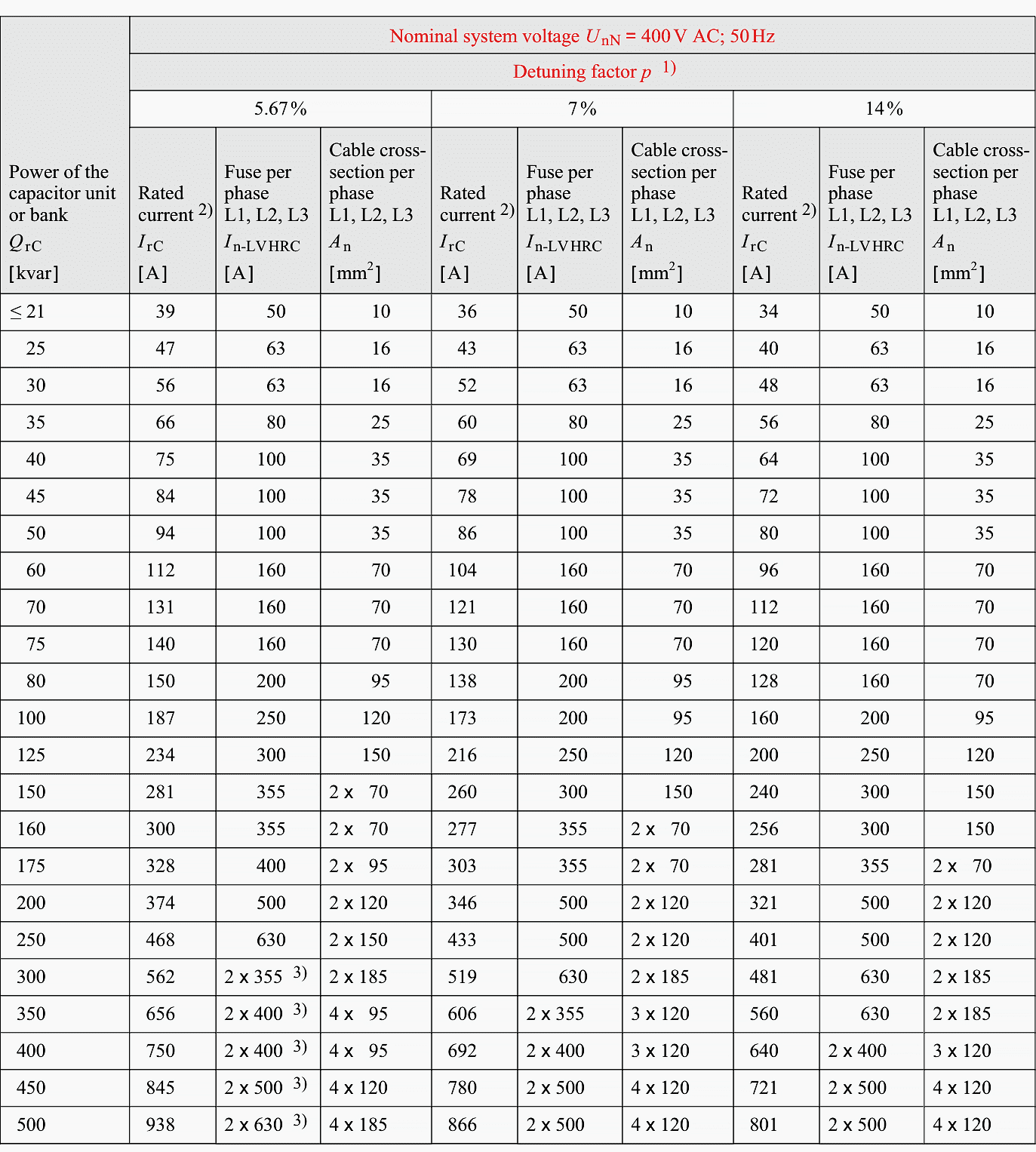
1) The detuning factor is the ratio of 50-Hz power of the reactor preceding the capacitor to the 50-Hz power of the capacitor.
2) The nominal current InC stated in Table 5 refers to the fundamental-frequency nominal power. Because of the harmonics, the following safety margins arise for the rated current IrC of detuned capacitor units (capacitor units with reactors):
IrC = 1.3 × InC if p = 5.67 %
IrC = 1.2 × InC if p = 7 %
IrC = 1.11 × InC if p = 14 %
At this design current, the circuit filter reactors are not yet disconnected due to excessive temperature
3) LV HRC fuses should only be recommended up to size 3 (for 500 V to 630 A and for 690 V to 500 A). For higher fuse currents, LV HRC fuse-switch-disconnectors of size 4 and 4a are required. Because their installation requires greater effort, two small LV HRC parallel fuse-switch-disconnectors are better in terms of installation engineering.
For other methods of installation, ambient temperatures and cable groupings, the cable must be precisely dimensioned.
The power section of a reactive-power compensation system for automatic PF correction must be dimensioned such that all components (switching devices, protection equipment, connection cables) reliably withstand the thermal and dynamic stresses caused by the fundamental current and any harmonic or switching impulse currents.
Sources: Planning Guide for Power Distribution Plants by Hartmut Kiank and Wolfgang Fruth
Related electrical guides & articles


Edvard Csanyi
Hi, I'm an electrical engineer, programmer and founder of EEP - Electrical Engineering Portal. I worked twelve years at Schneider Electric in the position of technical support for low- and medium-voltage projects and the design of busbar trunking systems.I'm highly specialized in the design of LV/MV switchgear and low-voltage, high-power busbar trunking (<6300A) in substations, commercial buildings and industry facilities. I'm also a professional in AutoCAD programming.
Profile: Edvard Csanyi

Air ckt breaker periodical maintenance details and types of Acb