
Estimated Study Time: 8 minutes

Materials Used
Porcelain is the most frequently used material for insulators. Insulators are made of wet, processed porcelain. The fundamental materials used are a mixture of feldspar (35%), china clay (28%), flint (25%), ball clay (10%), and talc (2%).
The alternative method is formation by extrusion bars that are machined into the desired shape. The shells are dried and dipped into a glaze material. After glazing, the shells are fired in a kiln at about 1200 8C. The glaze improves the mechanical strength and provides a smooth, shiny surface. After a cooling-down period, metal fittings are attached to the porcelain with Portland cement.
Toughened glass is also frequently used for insulators. The melted glass is poured into a mold to form the shell. Dipping into hot and cold baths cools the shells.
This thermal treatment shrinks the surface of the glass and produces pressure on the body, which increases the mechanical strength of the glass. Sudden mechanical stresses, such as a blow by a hammer or bullets, will break the glass into small pieces. The metal end-fitting is attached by alumina cement.
Insulator Strings
Most high-voltage lines use ball-and-socket-type porcelain or toughened glass insulators. These are also referred to as ‘‘cap and pin.’’ The cross section of a ball-and socket-type insulator is shown in Figure 1.

Table 1 shows the basic technical data of these insulators. The porcelain skirt provides insulation between the iron cap and steel pin. The upper part of the porcelain is smooth to promote rain washing and cleaning of the surface.
The lower part is corrugated, which prevents wetting and provides a longer protected leakage path. Portland cement attaches the cup and pin. Before the application of the cement, the porcelain is sandblasted to generate a rough surface.
 clevis type, (b) ball-and-socket type")
A thin expansion layer (e.g., bitumen) covers the metal surfaces. The loading compresses the cement and provides high mechanical strength.
This acts as a mechanical fuse protecting the tower structure. The ball-and-socket insulators are attached to each other by inserting the ball in the socket and securing the connection with a locking key.
| Diameter | 25.4 cm | (10 in.) |
| Spacing | 14.6 cm | (5-3/4 in.) |
| Leakage distance | 305 cm | (12 ft) |
| Typical operating voltage | 10 kV | |
| Mechanical strength | 75 kN | (15 klb) |
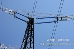
Several insulators are connected together to form an insulator string. Figure 2 shows a ball-and-socket insulator string and the clevis-type string, which is used less frequently for transmission lines.
Figure 3 shows representative fog-type insulators, the mechanical strength of which is higher than standard insulator strength. As an example, a 6 1/2 x 12 1/2 fog-type insulator is rated to 180 kN (40 klb) and has a leakage distance of 50.1 cm (20 in.).

| Line Voltage (kV) | Number of Standard Insulators |
| 69 | 4-6 |
| 115 | 7-9 |
| 138 | 8-10 |
| 230 | 12 |
| 287 | 15 |
| 345 | 18 |
| 500 | 24 |
| 765 | 30-35 |
Insulator strings are used for high-voltage transmission lines and substations. They are arranged vertically on support towers and horizontally on dead-end towers.
Table 2 shows the typical number of insulators used by utilities in the U.S. and Canada in lightly polluted areas.
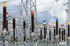
Post-Type Insulators

Post-type insulators are used for medium voltage and low voltage transmission lines, where insulators replace the cross-arm. However, the majority of post insulators are used in power substations where insulators support conductors, bus bars, and equipment.
Example
A typical example is the interruption chamber of a live tank circuit breaker. Typical post-type insulators are shown in Figure 4. Older post insulators are built somewhat similar to cap-and-pin insulators, but with hardware that permits stacking of the insulators to form a high-voltage unit. These units can be found in older stations.
Modern post insulators consist of a porcelain column, with weather skirts or corrugation on the outside surface to increase leakage distance.
For indoor use, the outer surface is corrugated. For outdoor use, a deeper weather shed is used. The end-fitting seals the inner part of the tube to prevent water penetration.
Figure 4 shows a representative unit used at a substation. Equipment manufacturers use the large post-type insulators to house capacitors, fiber-optic cables and electronics, current transformers, and operating mechanisms. In some cases, the insulator itself rotates and operates disconnect switches.
Post insulators are designed to carry large compression loads, smaller bending loads, and small tension stresses.
Long Rod Insulators
The long rod insulator is a porcelain rod with an outside weather shed and metal end fittings. The long rod is designed for tension load and is applied on transmission lines in Europe. Figure 5 shows a typical long rod insulator.

These insulators are not used in the U.S. because vandals may shoot the insulators, which will break and cause outages. The main advantage of the long rod design is the elimination of metal parts between the units, which reduces the insulator’s length.
REFERENCE: George G. Karady, Richard G. Farmer – Insulators and Accessories
Related electrical guides & articles


Edvard Csanyi
Hi, I'm an electrical engineer, programmer and founder of EEP - Electrical Engineering Portal. I worked twelve years at Schneider Electric in the position of technical support for low- and medium-voltage projects and the design of busbar trunking systems.I'm highly specialized in the design of LV/MV switchgear and low-voltage, high-power busbar trunking (<6300A) in substations, commercial buildings and industry facilities. I'm also a professional in AutoCAD programming.
Profile: Edvard Csanyi

how ceramic is soldered in the stainless steel? what are the methods and machines?
May 20, 2022
I have noticed on many power-grid poles that many insulators are not being used in a vertical position. Is true or not true that when an insulator is used at an angle or horizontal position, there is a small leakage of power to ground?
Insulators can be either porcelain or glass cap or composite type suitable for ACSR 240/40 with rated tensile strength over 83KN.
Insulators are to be rated for 33kV overhead lines.
Insulators are to be complete with their metal fittings.
Difference between longrod Porcelain vs composite porcelain. Which one is the best.
Very useful articles, I m 25 yrs in manufacturing of EHV- process.
Please sign me up – I am new at this, in the middle of the Mojave desert (Ridgecrest, Ca. 93555)
My address is 1225 Rebecca Ave.
Ridgecrest, Ca.
93555
Is that right ” One insulator is equal to the value of 1kv ” and Counting number of insulators in the Transmission line at one tower on one circuit provides how much the line voltage is?