
Estimated Study Time: 14 minutes
IEC 60364 & System Earthings
Choice of system earthing affects not only dependability (in the largest sense) but also installation, in particular with respect to the low voltage switchgear to be implemented. The three system earthings internationally used and standardized by IEC 60364 have as their common objective the quest for optimum safety.
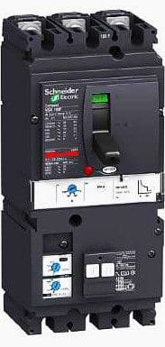
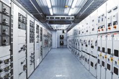
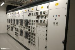
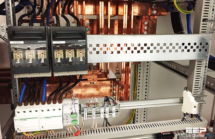 How choice of system earthing affects low voltage switchgear? (photo credit: Edvard CSANYI)
As regards protection of persons, the 3-phase systems are equivalent if all installation and operating rules are complied with. In view of the characteristics specific to each system, no one system can be preferred over another!
1. TN system
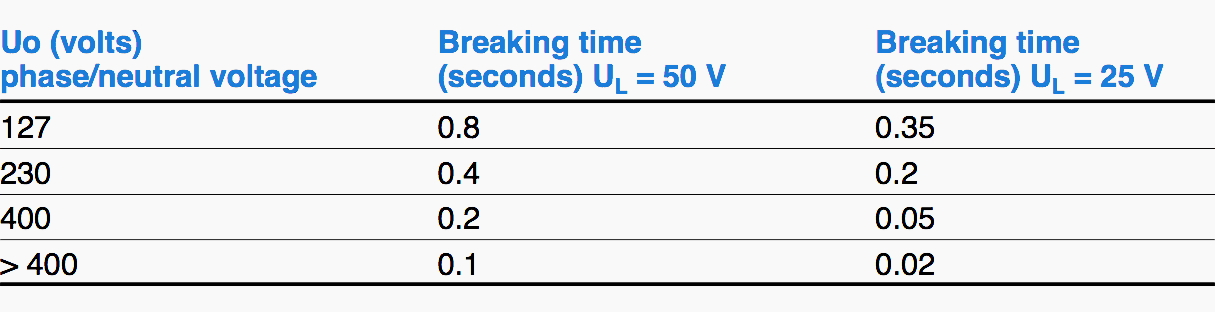
In this system the short circuit protection devices – SCPDs (circuit-breaker or fuses) generally provide protection against insulation faults, with automatic tripping according to a specified maximum breaking time (depending on phase-to-neutral voltage Uo. See Fig. 1).
With circuit breaker
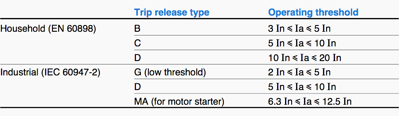
Circuit breaker tripping occurs at a level determined by the type of the tripping release (see Fig. 2). As soon as the fault current exceeds the threshold of the short-circuit protection trip release (generally “instantaneous”), opening occurs in a time far shorter than specified maximum breaking time, for example 5 s for distribution circuits and 0.4 s for terminal circuits.
When impedance of the source and cables is high, either low threshold trip releases must be used or RCDs associated with the SCPDs. These RCDs may be separate residual current devices or be combined with circuit-breakers (residual current circuit-breakers) of low sensitivity.
Their threshold must be:
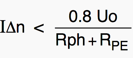
This solution is clearly not applicable with a TN-C type system earthing (the protective conductor being the same as the neutral one).
With fuses
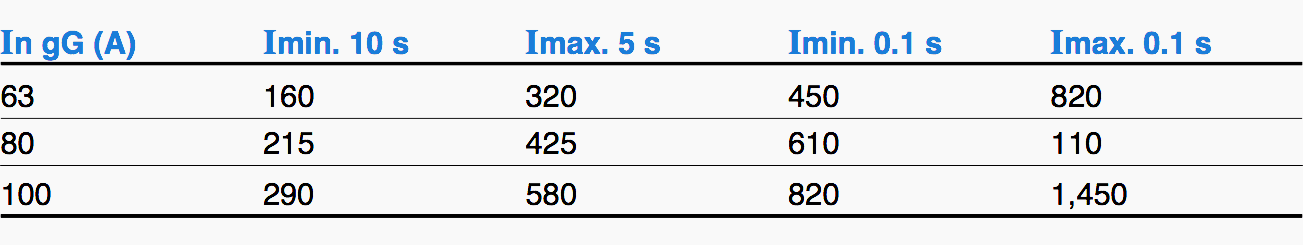
The fuses used for short-circuit protection are of the gG type and their time/current characteristics (see Fig. 3) are defined by standards (household fuses: IEC 60241, industrial fuses: IEC 60269). Checking suitability with the maximum specified breaking time therefore calls for individual validation of the ratings provided for each protection device.
If they are not suitable, either fault loop impedance must be reduced (increased cross-sections) or the fuse must be replaced by a low threshold or a residual current circuit-breaker.
2. TT system
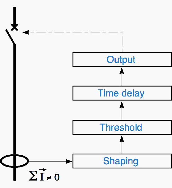
With this system, the small value of the fault currents (see previous section) does not allow the SCPDs to protect persons against indirect contacts. RCDs (see Fig. 4 and 5) need to be used, associated with circuit-breakers or switches (see IEC 60364 – paragraph 413.1.4.2).
These devices must meet the following standards in particular:
- IEC 60755: General rules
- IEC 61008: “Household” residual current switches
- IEC 61009: “Household” residual current SCPDs
- IEC 60947-2: “Industrial” residual current circuit-breakers
Their implementation must meet the objectives for:
- Protection of persons, i.e.
- Threshold I∆n ≤ UL/RA
- Breaking time ≤ 1s
- Continuity of service with thresholds and time delays enabling current and time discrimination
- Fire protection with I∆n ≤ 300 mA
3. IT system
Remember that in the event of a double fault, safety of persons is provided by the SCPDs. When the first insulation fault occurs, the calculation proved there was no risk (contact voltage lower than limit safety voltage).
Automatic de-energising is therefore not compulsory: This is the main advantage of this system.
Locating the first fault for repairs (curative maintenance) is considerably simplified by the use of a Ground Fault Location Device (GFLD).
Predictive maintenance, based on the monitoring (recording) of variations in insulation impedance of each circuit, is also possible.
LV networks, using the IT system, which take their origin at a MV/LV transformer, must be protected against risks of insulation faults between MV and LV by a “surge limiter“.
Finally, to fix the potential of the LV network with respect to the earth (short network supplied by a MV/LV transformer), an impedance can be installed between the transformer neutral and the earth. Its value in 50 Hz, of the order of 1,500 Ω, is very high in DC and in very low frequency so as not to obstruct insulation measurement and fault locating.
Operating principle of the IMDs
A fault on a circuit results in a drop in insulation, or more precisely in resistance of the network compared with earth. In France, the IMDs and GFLDs have to comply with manufacturing standard UTE 63080.
Injection of a DC current ensures continuous knowledge of network insulation resistance. If this resistance drops below a pre-set threshold, then the IMD reports the fault.
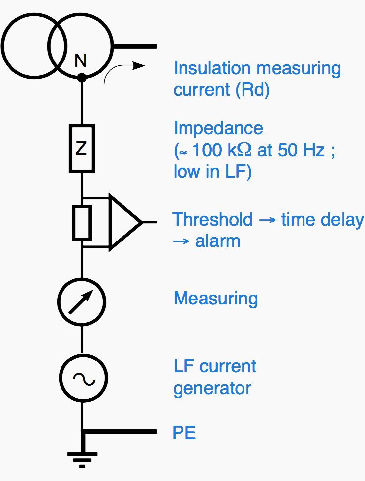
Injection of low frequency AC current (F ≈ a few hertz) monitors fault resistance but with a distorsion due to the presence of network leakage capacitites. This minor drawback compared with injection frequency, is made up for by an advantage in first fault locating (one single injection device).
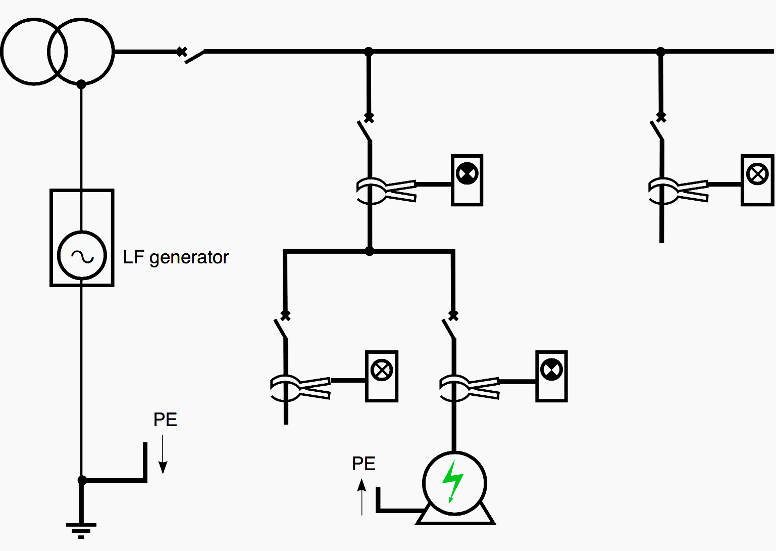
Operating principle of the GFLDs
The most common solution is to inject an identifiable current (with a frequency other than network one). The generator can be the IMD.
Then, by means of magnetic Current Sensors (toroid transformers and/or clamp-on probe) associated with an amplifier tuned to the injected current frequency, it is possible to trace its path up to the fault (see Fig. 7).
Finally, another solution is also used, which consists in comparing, constantly and for each feeder, the value of its resistance with a pre- defined or programmable threshold value.
This solution, computerized, enables the following actions, both locally and remotely:
- Reporting of the first fault (IMD)
- Then locating of this fault (GFLD) to put it right (curative maintenance) (see Fig. 8)
- And knowledge of insulation evolution in time, feeder by feeder, to take action on feeders with abnormal insulation drops (predictive maintenance)
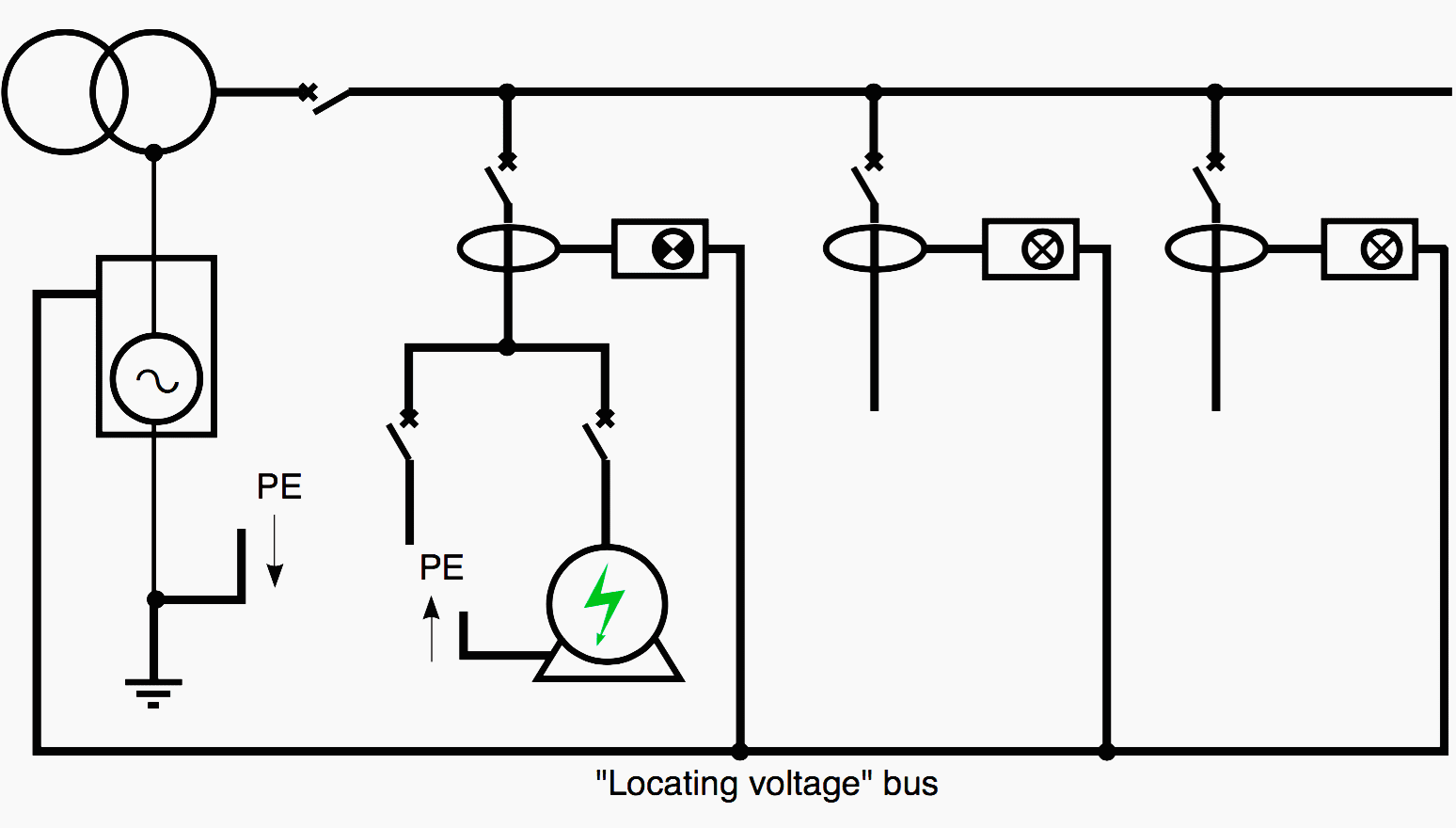
The locating current flowing in the conductors is detected by Current Sensors (CS). Each load comprising a discriminating amplifier (set to the frequency and phase of the locating current) calculates the resistance and capacity of the circuit (with the voltage and phase whose reference it obtains via a bus) and indicates the presence of the fault.
Surge limiters
Surge limiters are connected between a live conductor (neutral or phase) of the installation and the earth. Their arcing voltage Ue must therefore be adapted to the assembly planned:
Thus there are two models for a 50 Hz 230/400 V network:
- 250 V for connection to the neutral (400 V < Ue ≤ 750 V)
- 400 V for connection to a phase (700 V < Ue ≤ 1,100 V)
Their purpose is two fold:
- Limit voltage on the LV network on MV/LV disruptive breakdown in the distribution transformer. In this case, the limiter must flow off to earth the “residual” current of the MV network,
- Limit lightning overvoltages.
This accounts for their characteristics, for example for the 250 V model:- Rate voltage: 250 V
- Disruptive breakdown voltage at 50 Hz: Min 400 V, max 750 V
- Disruptive breakdown voltage according to the 1.2/50 μs wave: û < 1,570 V
- Ilightning: 20 times 2,500 A (8/20 μs wave): Without short-circuiting
- I50Hz:
20,000 A / 0.2s,
5,000A /5s,
1,200A /2mn
The limiters marketed under the Schneider Electric brand can withstand 40 kA/0.2 s.
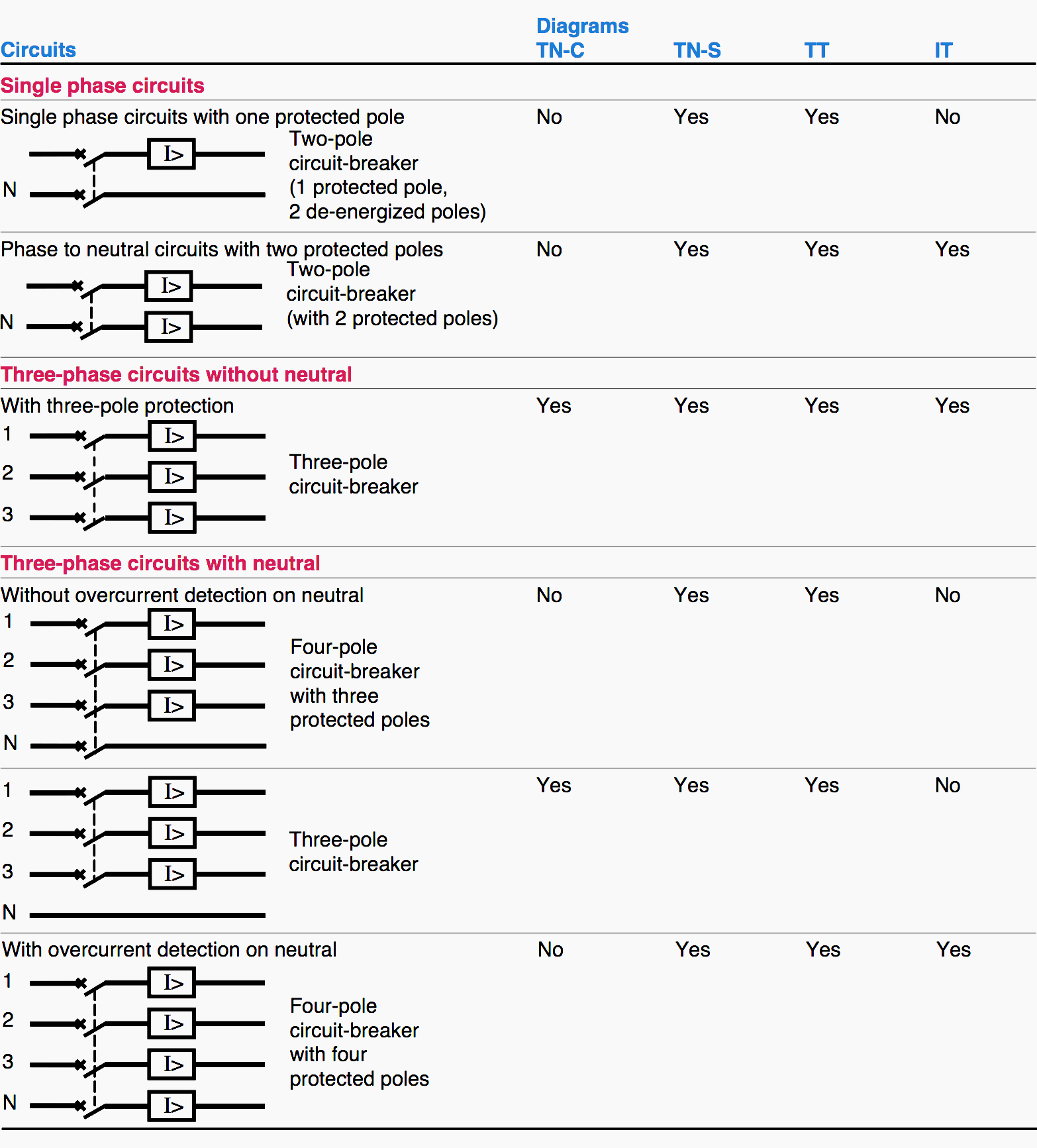
Neutral protection according to the system earthing
The neutral must be broken by a multi-pole device:
- In TT and TN, if neutral cross-section is less than phase cross-section
- In terminal distribution in view of the Neutral/ Phase reversal risk
The neutral must be protected and broken:
- In IT for intervention of the protection device on the double fault, with one of the faults possibly on the neutral
- In TT and TN-S if neutral cross-section is less than phase cross-section
To prevent risks, a local equipotentiality and an earth connection must be provided for each zone/consumer.
Figure 9 shows which types of circuit-breaker should be used for which system earthing. Note that TT and TN can use the same devices (with an additional residual current module in TT).
Reference // System earthings in LV by R. Calvas and B. Lacroix (Schneider Electric)
Related electrical guides & articles


Edvard Csanyi
Hi, I'm an electrical engineer, programmer and founder of EEP - Electrical Engineering Portal. I worked twelve years at Schneider Electric in the position of technical support for low- and medium-voltage projects and the design of busbar trunking systems.I'm highly specialized in the design of LV/MV switchgear and low-voltage, high-power busbar trunking (<6300A) in substations, commercial buildings and industry facilities. I'm also a professional in AutoCAD programming.
Profile: Edvard Csanyi

Good day, I a have been with the EPP updates for years your support to the Power system Engineering keeps me of age in these field but still want to communicate with you via email please Thank you.
I am a electrical technician from sri lanka. specialy This is a very useful technical programme for me.thank u very much mr.edvard.
Dear thanks a lot for updating me with this information on earthing implementation but still it will be very helpfull if you send me more basic easier info on medium voltage earthing by the we are running small 11 KV utility power supply in single line of 3.5 MW production line our main power cut is in earth fault and Corona effect when raining please advice
I like it. thanks!
Sir please explain about E-CAD
Very good information.
merci edvard pour toute ces riche informations
regards
Good afternoon
I ask for information about the connection in the ladder tray on the grounding cable
is there a regulator
thank you
Very interesting!
Thanks
You’re welcome Angel, I’m glad you like it.
Knowledgeable electrical information elaborated. Thumps up.
Thank you!
I am interesting with these informations and your emails. I am thankful from these .
You can subscribe to either technical article notifications (http://eepurl.com/lmhNv) or our newsletter Weekly Digest (http://eepurl.com/houxM).
Extremely valuable information.
Thank you Ghazanfar.