
Estimated Study Time: 29 minutes
Why is CT Sizing Calculation Necessary
In the realm of electrical power systems, current transformers (CTs) play a vital role in accurately measuring and monitoring current levels. Proper sizing of CTs is essential to ensure their adequacy and enable reliable operation within specified limits. This article focuses on the calculation of CT sizing specifically for dual power overcurrent relays, aiming to ensure effective protection and fault detection in power systems.
 Never underestimate how important it is to choose the right CT size in fault detection and protection (photo credit: pfiffner-group.com)
Accurate current measurement forms the foundation of various functions within a power system, including fault detection, protection coordination, and equipment monitoring. The primary purpose of a CT is to step down high primary currents to manageable secondary currents proportional to the primary currents. This secondary current is then utilized for measurements by protective relays, meters, and other devices.
To ensure the effectiveness and reliability of these measurements, it is crucial to determine the appropriate CT size. Oversized CTs may result in insufficient resolution, leading to inaccurate measurements, while undersized CTs can become saturated and fail to accurately represent the primary current.
In the following sections, we will delve deeper into the intricacies of CT sizing, including understanding CT saturation, the accuracy limit factor (ALF), CT selection criteria, and provide an example of overcurrent relay setting calculations.
This comprehensive exploration aims to provide a practical understanding of CT sizing principles and guidelines for dual power overcurrent relays.
- Factors Influencing CT Sizing Calculations
- Optimizing CT Ratio Selection: Ensuring Accurate Current Measurement and Protection
- Optimizing CT Secondary Current Selection: Factors and Considerations
- Understanding Short Circuit Level and Its Significance in Current Transformer Sizing and Design
- Accurate Current Measurement: Understanding Accuracy Class Determination for Current Transformers (CTs) as per IEC 61869-2
- Understanding CT Ratings and Burden Considerations: Maintaining Accuracy and Avoiding Saturation
- CT Selection Criteria: Evaluating Apparent Voltage and Saturation for Accurate Current Measurement
- Calculation of Overcurrent Relay Settings Using SIA-C FANOX Make: An Illustrative Example
- BONUS! CT Theory and Standards IEC 600441 and IEC 61869-2
1. Factors Influencing CT Sizing Calculations
In this comprehensive guide, we delve into the various factors that influence CT sizing calculations and explore the key considerations for optimizing CT selection. We will discuss the importance of selecting the right CT ratio to ensure accurate current measurement and reliable protection functionality.
Additionally, we will examine the factors and considerations involved in choosing the appropriate CT secondary current.
Understanding the short circuit level and its significance in CT sizing and design will also be explored. The short circuit level, defined by the fault current and duration, is a crucial parameter used in CT sizing calculations. We will discuss how the short circuit level affects CT design and the importance of considering thermal withstand capabilities and time ratings.
We will discuss the significance of matching the CT burden with the CT’s nameplate rating to ensure accurate performance and avoid saturation. Lastly, we will touch upon the concept of CT saturation and Vsat (saturation voltage) as critical factors in CT performance.
Understanding the relationship between the apparent voltage at the CT secondary winding and the saturation voltage is crucial for selecting the appropriate CT and maintaining accurate current measurement.
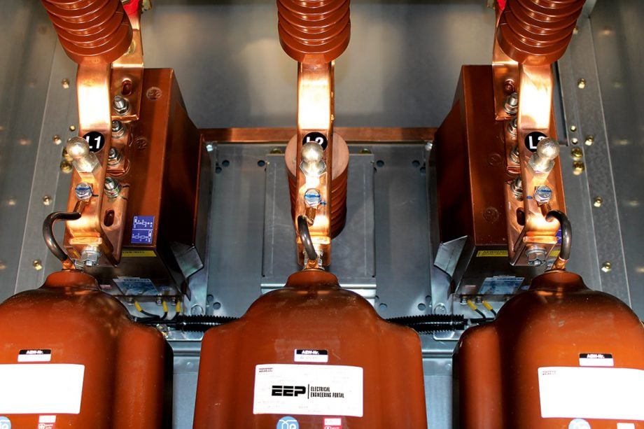
Figure 1 – Medium voltage current transformers

1.1 Optimizing CT Ratio Selection:
Ensuring Accurate Current Measurement and Protection:
Selecting the appropriate CT ratio is a crucial step in CT design! It is influenced by two key factors: the maximum load current and the maximum short circuit current. The CT ratio should ideally be greater than the rated current, typically around 120%.
This ensures that the CT can accurately measure current values under load conditions, which is essential for various protection functions that operate near the rated current, such as overload protection and inverse time protection.
Additionally, the CT ratio selection must also consider the maximum fault current level. It is important to ensure that the fault current level remains below the CT’s saturation point. Saturation occurs when the primary current exceeds the CT’s magnetic core capabilities, leading to inaccurate measurements.
The connected load plays a significant role in determining the saturation level, and the CT ratio should be chosen in a way that keeps the fault current within an acceptable range.
Proper CT ratio selection forms the foundation for reliable current measurement and plays a vital role in the overall performance of the protection system. Therefore, engineers must carefully analyze the system requirements, load characteristics, and expected fault currents to make informed decisions regarding CT ratio selection, ultimately ensuring accurate and effective operation of the current transformer.
Table 1 – Standard multi ratio current transformer taps as per IEEE C57.13

1.2 Optimizing CT Secondary Current Selection
Factors and Considerations
CT secondary ratings are typically available in two standard options: 1 Amp and 5 Amp. While 5 Amp CTs are more cost-effective to manufacture, it’s important to consider the burden they offer in terms of VA (volt-amperes) at a given load resistance. In comparison, 1 Amp CTs provide a lower VA burden on the secondary side.
The choice between 1 Amp and 5 Amp CTs depends on factors such as the length of the CT loop. In applications where the yard length is extensive, such as in high-voltage or extra-high-voltage switchgear installations, 1 Amp CTs are commonly used. This is because the lower secondary current helps mitigate voltage drops and power losses over longer distances.
Related electrical guides & articles


Muhammad Kashif
Muhammad Kashif Shamshad is an Electrical Engineer and has more than 17 years of experience in operation & maintenance, erection, testing project management, consultancy, supervision, and commissioning of Power Plant, GIS, and AIS high voltage substations ranging up to 500 kV HVAC & ±660kV HVDC more than ten years experience is with Siemens Saudi Arabia.Profile: Muhammad Kashif
