
Estimated Study Time: 18 minutes
The choice of a neutral earthing system
The choice of a neutral earthing system is dependent on requirements and objectives that are often contradictory to such an extent that sometimes several systems have to be created within one installation (islanding) in order to meet safety, maintainability, or operating requirements that are too dissimilar.
 Advice in choosing the right neutral earthing system for your installation
This technical article will not discuss the basics of neutral earthing systems, and it is considered that you are already familiar with the subject. Instead, it will focus on the characteristics that may influence electrical engineers’ decision to select the most suitable neutral earthing system.
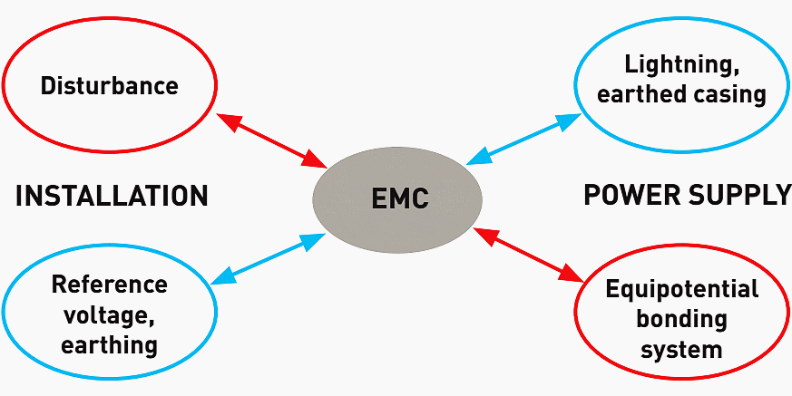
Don’t forget that the choice of the neutral earthing system has a direct effect on the electromagnetic compatibility (EMC) of the installation, so that will be covered too.
1. Characteristics of neutral earthing systems
The following paragraphs summarize the advantages and the disadvantages of each neutral earthing system.
1.1 TT system
General principle
Detection of a fault current running through the earth and disconnection of the power supply by a residual current device (RCD).

If insulation fault occurs on a receiver, the fault current If circulates in the fault loop. This circuit includes the fault impedance on:
- The exposed conductive part of the connected load,
- The connection of this exposed conductive part to the protective conductor,
- The protective conductor itself and
- Its earth connection (RA).
The fault loop is finally closed by the transformer windings and the power supply circuit.
Advantages of TT system
- Simplicity (very few calculations when installing).
- Extension with no need to calculate the lengths.
- Low fault currents (fire safety).
- Very little maintenance (apart from regular testing of the RCDs).
- Safety of people when portable devices are supplied or if earthing is defective (with 30 mA RCDs).
- Operation on a source at low prospective current ik (generator set).
Disadvantages of TT system
- No differential discrimination if only one device at supply end of installation
- Need for RCDs on each outgoing line to obtain horizontal discrimination (cost)
- Risk of false tripping (overvoltages)
- Interconnection of exposed conductive parts to a single earth connection (widespread installations) or RCD needed for each group of exposed conductive parts
- Level of safety dependent on the value of the earth connections
Important notes for TT system
- Voltage surge protectors recommended for overhead distribution
- Possibility of linking the power supply earth connection and that of the exposed conductive parts for private MV/LV transformer (check breaking capacity of RCDs)
- Need to control equipment with high leakage currents (separation, islanding)
- Importance of establishing and ensuring durability of earth connections (safety of people)
- Ensure the earth values and tripping thresholds of the RCDs are checked periodically
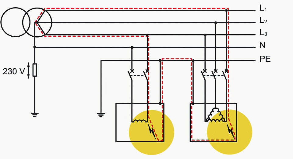
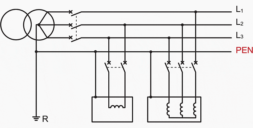
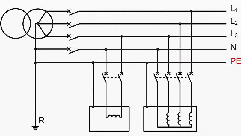
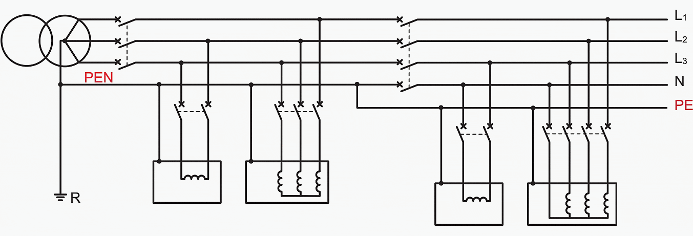
1.2 TN system
General principle
The fault current changes to a short-circuit current which is broken by the overcurrent protection devices, and the exposed conductive parts are kept below a safe voltage threshold.
In TN systems, a point on the power supply, generally the transformer neutral, is earthed. The exposed conductive parts of the installation are connected to the same point by a protective conductor.
When both variants cohabit in the same installation, the term TN-C-s can be used (see connections), remembering that the TN-C system must always be upstream of the TN-S system.

If insulation fault occurs at any point in the installation affecting a phase conductor and the protective conductor or an exposed conductive part, the power supply must be cut off automatically within the specified breaking time t while complying with the condition:
Zs × Ia ≤ U0
Where:
- Zs – impedance of the fault loop comprising the power supply line, the protective conductor and the source (transformer windings).
- Ia – operating current of the protection device within the specified time
- U0 – nominal phase/earth voltage
Advantages of TN system
- Low cost (protective devices are used for fault currents and overcurrents)
- The earth connection has no effect on the safety of people
- Low sensitivity to disturbance (good equipotentiality, neutral earthed)
- Low sensitivity to high leakage currents (heating, steam, computing equipment)
Disadvantages of TN system
- High fault currents (generation of disturbance and risk of fire in particular with TN-C system)
- Need for accurate calculation of lines
- Risk in the event of refurbishment extensions or uncontrolled use (qualified staff)
Important notes for TN system
- The protection conditions must be checked: at the design stage (calculation), on commissioning, periodically and if the installation is modified
- Practical checking requires special test equipment (measurement of the ik at the end of the line)
- The use of residual current devices enables the fault currents to be limited (check the breaking capacity) and risks not provided for by the calculations to be overcome (breaking of the protective conductors, line lengths of mobile loads, etc.)
1.3 IT system
General principle
Keeping the 1st fault current at a very low value limits the voltage rise of the exposed conductive parts, and there is thus no need for disconnection. However, 2nd fault is a different story.
Let’s see what happens with the 1st fault in this neutral earthing system.
1st fault – No danger for people

The current of the 1st fault (If) is limited by the sum of the resistances of the earth connections of the power supply (RB), the exposed conductive parts (RA) and the impedance (Z).
If = U0 / ( RA+RB+Z) = 230 / (30+10+2000) = 0,112 A
The non-breaking condition must be checked, ensuring that the current will not increase the exposed conductive parts to a voltage higher than the voltage limit UL. The following is therefore required: RA × If < 50 V, i.e. in the example: 30 × 0.112 = 3.36 V.
The exposed conductive parts will not reach a dangerous voltage and non-breaking is permitted.
2nd fault – Short circuit
In the event of a 2nd fault affecting another phase, on the same or another exposed conductive part, a loop is created by the exposed conductive parts of the faulty receivers, the protective conductors and the power supply conductors.
If there is a fault, the voltage of the neutral may increase to that of the faulty phase (phase-to-neutral voltage). The voltage of the other phases will tend to increase towards the value of the phase-to-phase voltage.
It is therefore advisable not to supply devices between phase and neutral in IT systems and thus not to distribute the neutral.
Advantages of IT system
- Continuity of service (no breaking on 1st fault).
- 1st fault current very low (fire protection).
- Fault current causes little disturbance.
- Operation on sources at low prospective current ik (generator set).
- Supply of receivers sensitive to fault currents (motors).
Disadvantages of IT system
- Installation cost (protected neutral, Pim, voltage surge protectors).
- Operating cost (qualified staff, location of faults).
- Sensitivity to disturbance (poor equipotentiality with earth).
- Risks on 2nd fault:
- Short-circuit overcurrents.
- Disturbance (rise in earth voltage).
- Appearance of a phase-to-phase voltage (if neutral distributed).
Important notes for IT system
- Indication of the 1st fault is mandatory and a search for the cause must be undertaken immediately.
- The situation of a 2nd fault must be avoided in view of the risks involved.
- Protection by voltage surge protectors is essential (risk of rise in earth voltage).
- It is advisable to limit the scale of it installations to what is strictly necessary (islanding).
The following tables give general rules for choosing the neutral earthing system according to the installation, the loads and the operating conditions.
Choosing the overall system based on this single application would be to risk making the wrong choice for the rest of the installation.
Table 1 – Recommended system acc. to the type and characteristics of the installation
| Type and characteristics of the installation | Recommended system |
| LV public distribution system | TT (TN on request) |
| Widespread system with poor earth connections | TT |
| Supply via transformer with low ik | |
| Generator set (temporary installation) | |
| Overhead line system | |
| System subject to disturbance (area subject to lightning) | TN |
| System with high leakage currents | |
| Generator set (temporary power supply) | TN-S |
| Generator set (emergency power supply) | IT |
| Emergency source for safety circuits in buildings open to the public |
Table 2 – Recommended system acc. to types of receiver and operating conditions
| Types of loads and operating conditions | Recommended system |
| Numerous mobile or portable devices | TT |
| Installations with frequent modifications | |
| Site installations | |
| Old installations | |
| Areas where there is a risk of fire | |
| Electronic and computing equipment | TN-S |
| Equipment with auxiliaries (machine tools) | |
| Handling equipment (hoists, cranes, etc.) | |
| Devices with low insulation (cooking, steam appliances, etc.) | |
| Installations with high leakage currents (marinas, etc.) | |
| Areas where there is a risk of fire | IT |
| Control and monitoring installations with large numbers of sensors | |
| Installations with requirement for continuity (medical, pumps, ventilation, etc.) | |
| Devices that are sensitive to leakage currents (risk of damage to windings) |
2. Neutral earthing system and EMC
The choice of the neutral earthing system has a direct effect on the electromagnetic compatibility (EMC) of the installation:
- The consequences of a lighting strike are partly dependent on the situation of the power supply in relation to earth, defined by the first letter (I or T).
- The transmission of conducted or emitted high frequency disturbance depends on the connection of the exposed conductive parts of the installation and their equipotentiality, defined by the second letter (T or N).
The energy transmission distances require a common voltage reference that can be accessible from the source to the load and can discharge disturbance such as lightning. Only the earth meets these conditions!
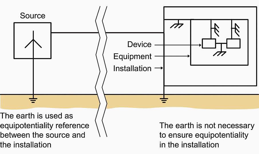
Locally, the earth is not necessary for the equipotentiality of an installation. It is the equipotential bonding system which provides this equipotentiality. Thus when the energy source is nearby or standalone (batteries, solar panels, generator set, etc.) it is not necessary to earth the power supply and the installation.
High altitude weather stations and isolated transmitters use this principle.

Let’s see now advantages and disadvantages of the neutral earthing systems in relation to EMC:
2.1 TT system
Advantages
- The neutral voltage is fixed.
- The fault currents are low.
Disadvantages
- Source earth connection and load earth connection are separated and less equipotential. impedance of the load earth connection can be high.
- PE conductor does not constitute a reliable voltage reference, resulting in the need for additional equipotential links.
- Lightning strike giving differential mode overvoltage (dissymetry of the system).
2.2 IT system
Advantages
- The fault currents are low.
- Good protection against conducted lightning, but risk of sparkover on the neutral impedance, resulting in the need for a surge voltage protector.
Disadvantages
- “Load” earth voltage not fixed in relation to the source and consequently not fixed in relation to that of the exposed conductive parts.
- Increase in earth voltage (direct lightning strike) or after the 1st fault: loss of reference for electronic devices.
- Circulation of permanent currents by capacitive coupling between live and earth conductors.
2.3 TN-S
Advantages
- A single “source” and “load” voltage reference, the earth is not used as a conductor, and good equipotentiality of the exposed conductive parts.
- Low impedance of the protection circuit due to the need to carry high fault currents.
Disadvantages
- Specific installation rules and equipment (5 wires).
- Possible rejection of disturbance on the neutral if the equipotentiality is uncertain between the neutral and the Pe conductor or if their paths are different.
- High fault currents.
- Lightning strike giving differentiel mode overvoltage (dissymetry of the system).
2.4 So, which system is the best?
It is generally agreed that the TN-s system is the best compromise in terms of EMC. It is easy to the make up for limitations of this system by the additional use of voltage surge protectors that combine common and differential modes.
Use, on each outgoing circuit, of RCBOs compatible with the leakage currents will limit the currents in the event of a fault.
The TN-C system is not recommended due to the circulation of high fault currents in the PEN conductor.
Source: Electrical energy supply by Legrand
Related electrical guides & articles


Edvard Csanyi
Hi, I'm an electrical engineer, programmer and founder of EEP - Electrical Engineering Portal. I worked twelve years at Schneider Electric in the position of technical support for low- and medium-voltage projects and the design of busbar trunking systems.I'm highly specialized in the design of LV/MV switchgear and low-voltage, high-power busbar trunking (<6300A) in substations, commercial buildings and industry facilities. I'm also a professional in AutoCAD programming.
Profile: Edvard Csanyi

Hi Sir,
I would like to ask you for some question: for MDB earthing system TN-C-S, the Neutral-earth bonding require to support by insulation support o can mount to MDB flame ?
and which support better between insulate support & not insulate support for Neutral-earth bonding ?
I would like to that you for your daily Electrical “news paper” that really in-rich every EE knowledge and background with a wide range of power engineering subjects