
Estimated Study Time: 12 minutes
Single line diagram
The starting point for planning a switchgear installation is its single line diagram. This indicates the extent of the installation, such as the number of busbars and branches, and also their associated apparatus.
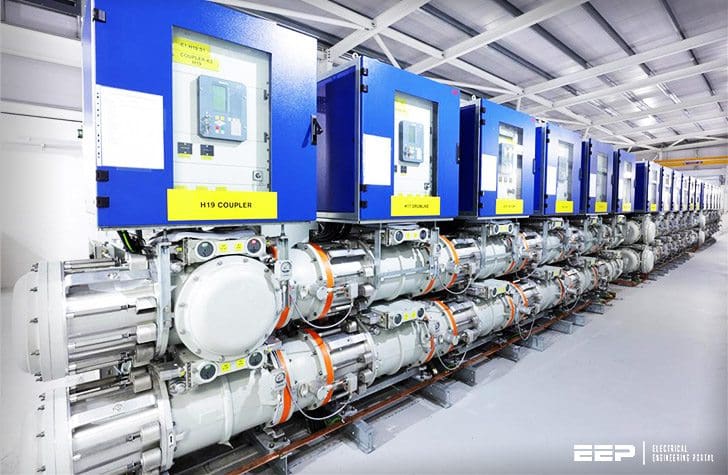 Circuit configurations for HV and MV switchgear installations (on photo: Ardnacrusha 110 kV GIS substation, Ireland; credit: ABB)
The most common circuit configurations of high and medium-voltage switchgear installations are shown in the form of single line diagrams next paragraphs.
Circuit configurations
The circuit configurations for high- and medium-voltage switchgear installations are governed by operational considerations. Whether single or multiple busbars are necessary will depend mainly on how the system is operated and on the need for sectionalizing, to avoid excessive breaking capacities.
When drawing up a single line-diagram, a great number of possible combinations of incoming and outgoing connections have to be considered. The most common ones are shown in the following diagrams.
- Most common circuit configurations
- Special configurations, mainly outside Europe
- Configurations for load-centre substations
1. The most common circuit configurations
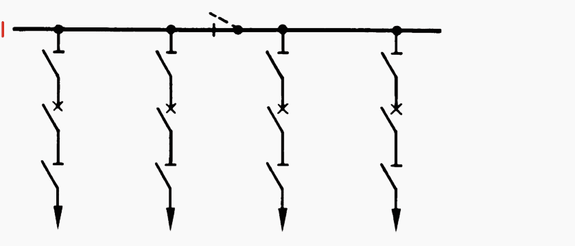
Single busbars
Suitable for smaller installations. A sectionalizer allows the station to be split into two separate parts and the parts to be disconnected for maintenance purposes.
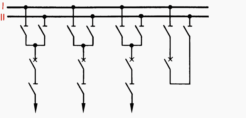
Double busbars
Preferred for larger installations. Advantages: cleaning and maintenance without interrupting supply. Separate operation of station sections possible from bus I and bus II. Busbar sectionalizing increases operational flexibility.
Double busbars in U connection
Low-cost, space-saving arrangement for installations with double busbars and branches to both sides.
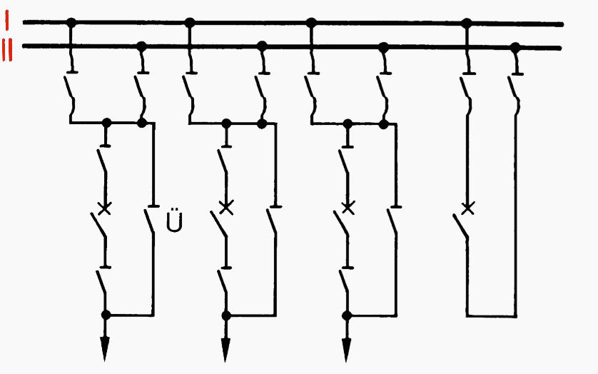
Composite double bus/bypass bus
This arrangement can be adapted to operational requirements. The station can be operated with a double bus, or with a single bus plus bypass bus.
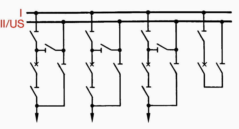
Double busbars with draw-out circuit-breaker
In medium-voltage stations, draw-out breakers reduce downtime when servicing the switchgear; also, a feeder isolator is eliminated.
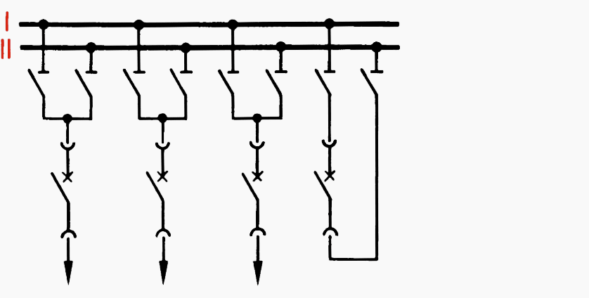
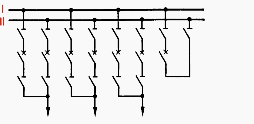
Two-breaker method with draw-out circuit-breakers
Draw-out circuit-breakers result in economical medium-voltage stations. There are no busbar isolators or feeder isolators. For station operation, the draw-out breaker can be inserted in a cubicle for either bus I or bus II.
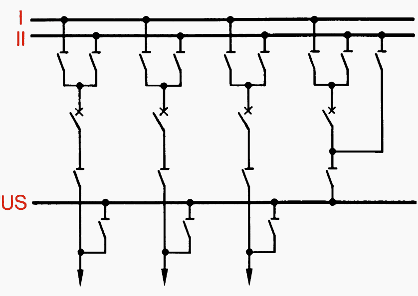
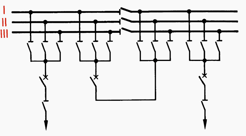
Double busbars with bypass busbar (US)
The bypass bus is an additional busbar connected via the bypass branch. Advantage: each branch of the installation can be isolated for maintenance without interrupting supply.
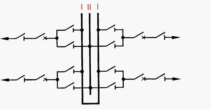
Triple (multiple) busbars
For vital installations feeding electrically separate networks or if rapid sectionalizing is required in the event of a fault to limit the short-circuit power. This layout is frequently provided with a bypass bus.
2. Special configurations, mainly outside Europe
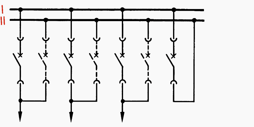
Double busbars with shunt disconnector
Shunt disconnector “U” can disconnect each branch without supply interruption. In shunt operation, the tie breaker acts as the branch circuit-breaker.
Two-breaker method with fixed switchgear
Circuit-breaker, branch disconnector and instrument transformers are duplicated in each branch. Busbar interchange and isolation of one bus is possible, one branch breaker can be taken out for maintenance at any time without interrupting operation.
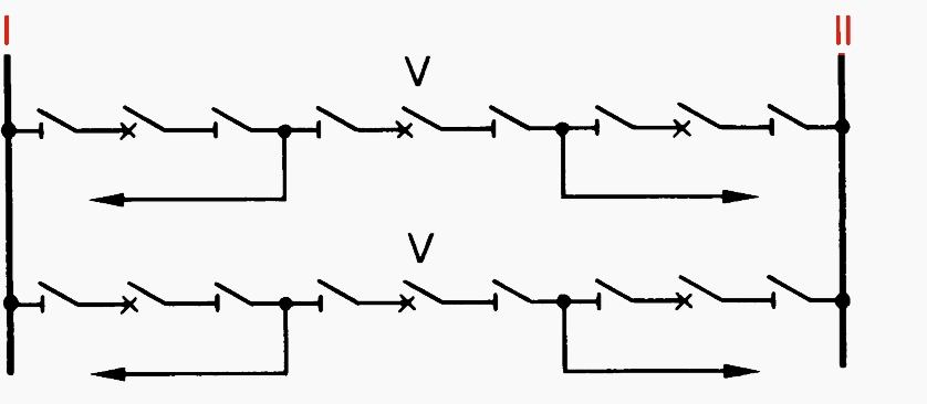
1 ½ breaker method
Fewer circuit-breakers are needed for the same flexibility as above. Isolation without interruption. All breakers are normally closed. Uninterrupted supply is thus maintained even if one busbar fails.
The branches can be through-connected by means of linking breaker V.
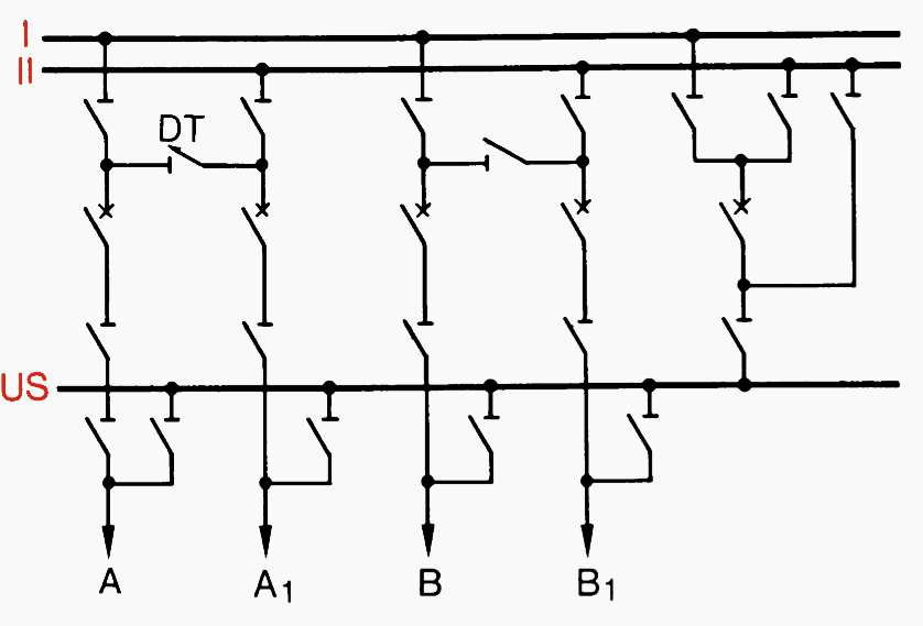
Cross-tie method
With cross-tie disconnector “DT”, the power of line A can be switched to branch A1, bypassing the busbar. The busbars are then accessible for maintenance.
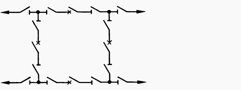
Ring busbars
Each branch requires only one circuit-breaker, and yet each breaker can be isolated without interrupting the power supply in the outgoing feeders.
The ring busbar layout is often used as the first stage of 1 ½ breaker configurations.
3. Configurations for load-centre substations
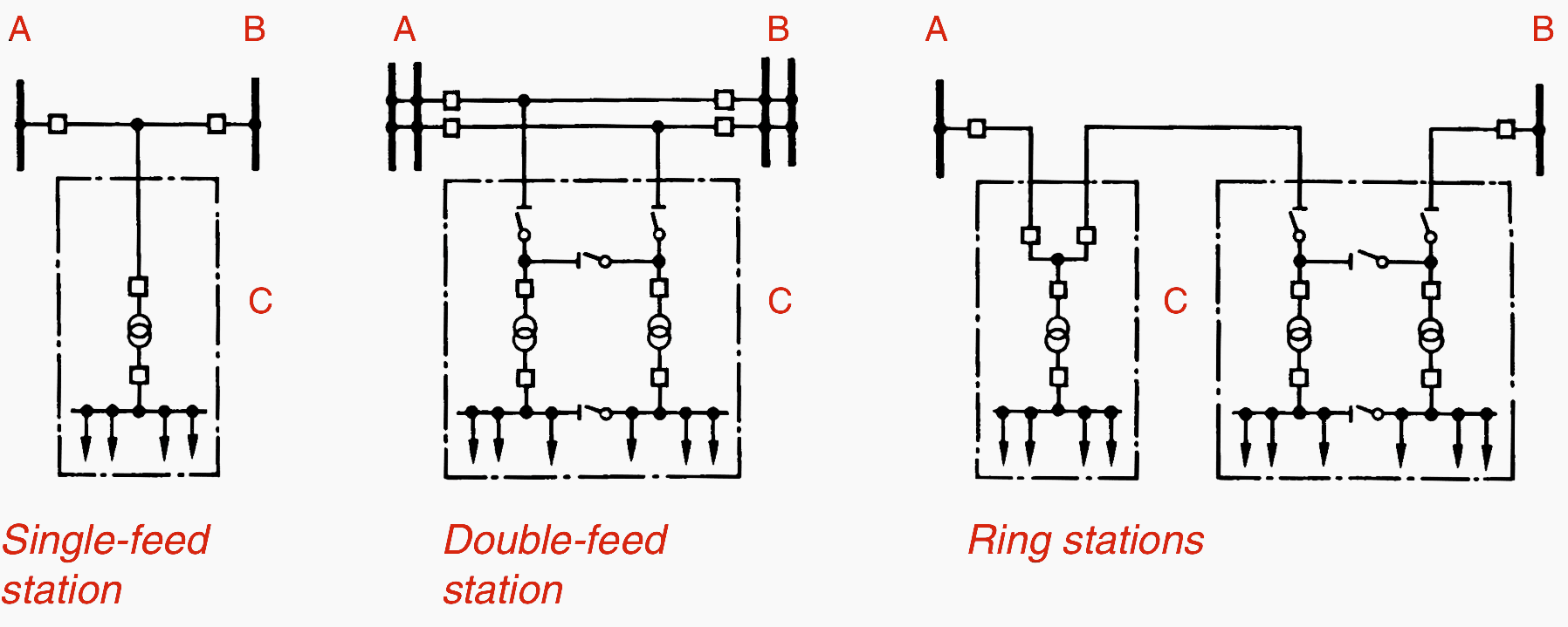
Where:
- A and B – Main transformer station,
- C – Load-centre substation with circuit-breaker or switch disconnector.
Switch-disconnectors are frequently used in load-centre substations for the feeders to overhead lines, cables or transformers. Their use is determined by the operating conditions and economic considerations.
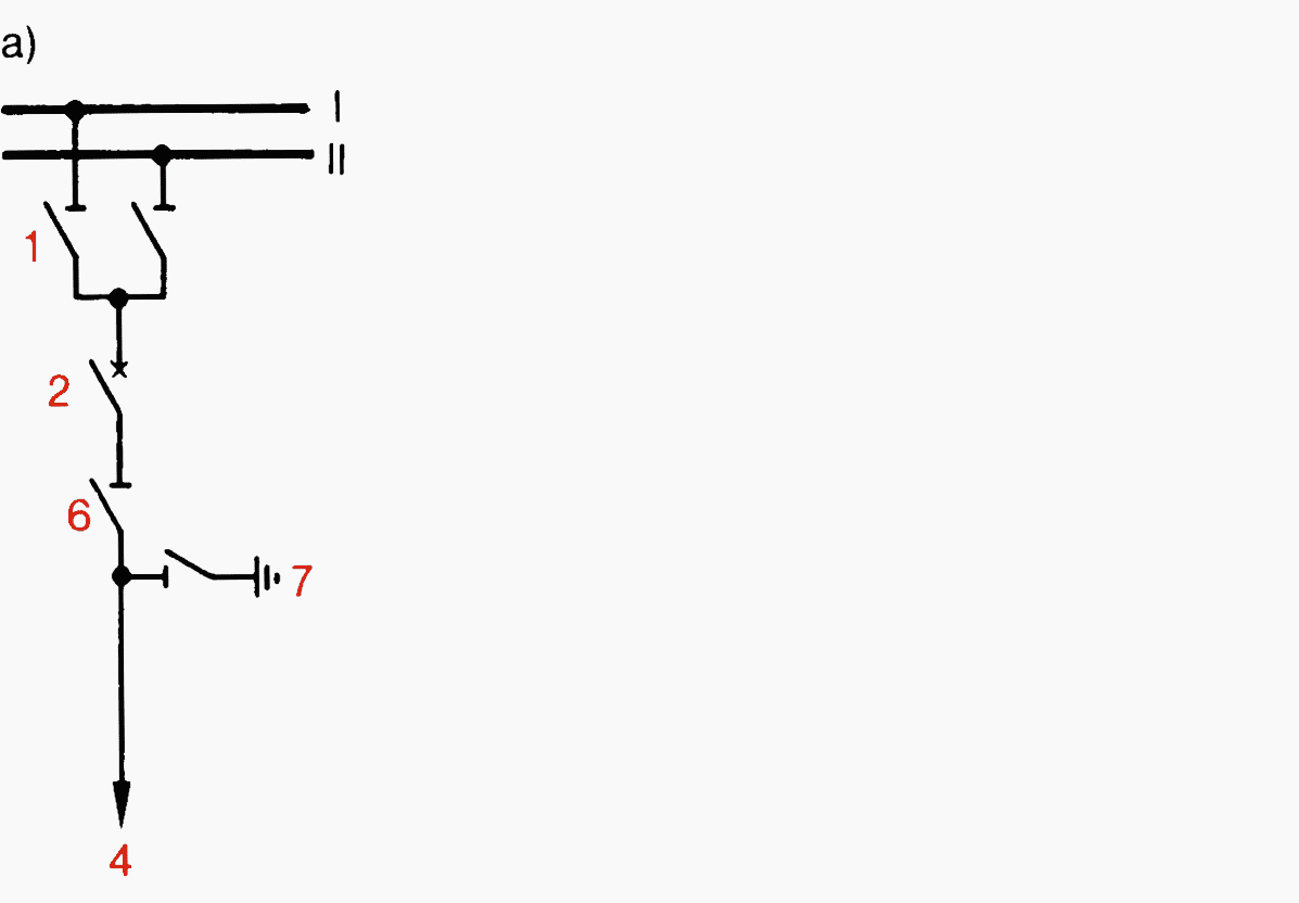
3a. Branch connections, variations a) to d)
a) Overhead-line and cable branches
Earthing switch 7 eliminates capacitive charges and provides protection against atmospheric charges on the overhead line.
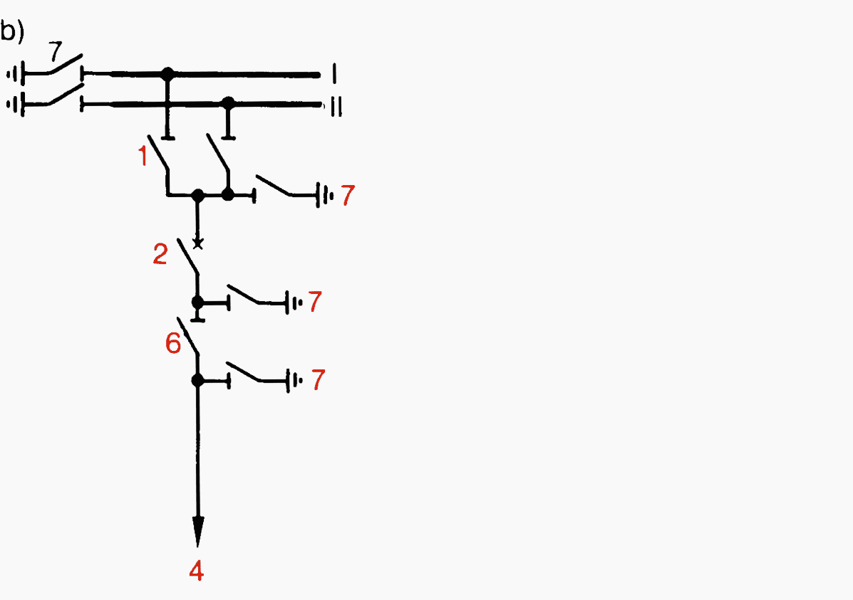
b) Branch with unit earthing
Stationary earthing switches 7 are made necessary by the increase in short-circuit powers and (in impedance-earthed systems) earth-fault currents.
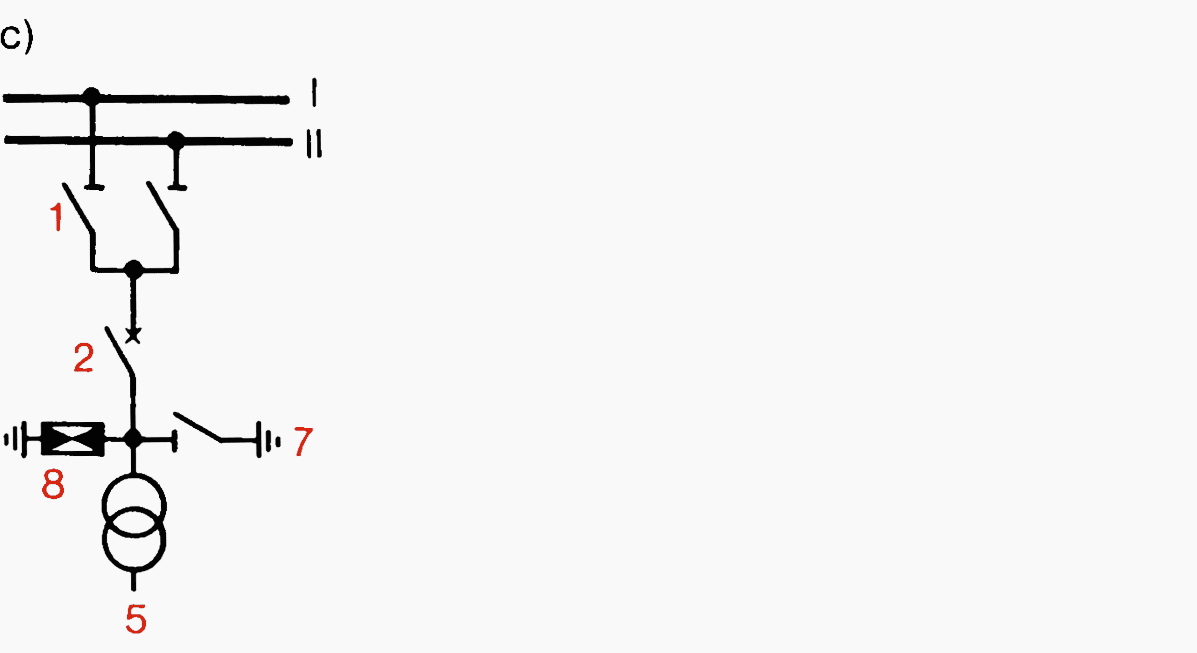
c) Transformer branches
Feeder disconnectors can usually be dispensed with in transformer branches because the transformer is disconnected on both h.v. and l.v. sides. For maintenance work, an earthing switch 7 is recommended.
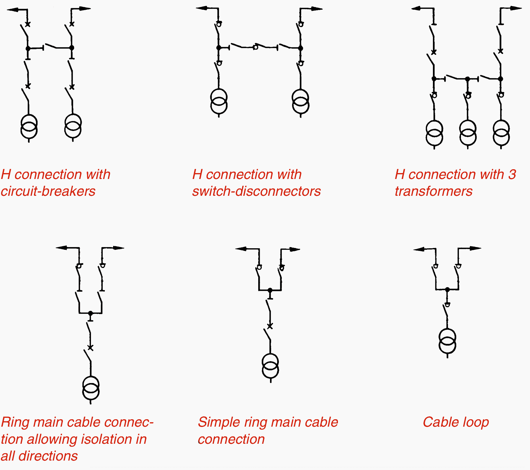
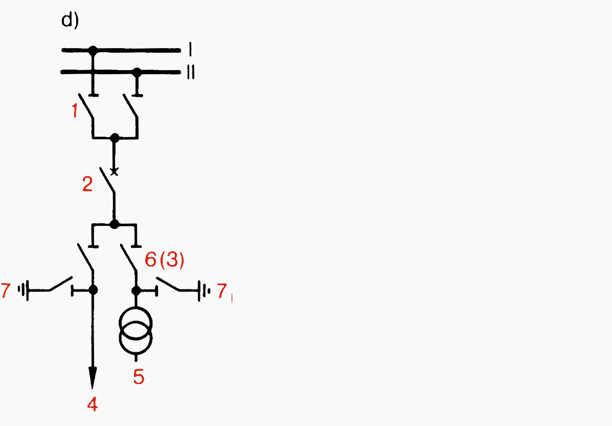
d) Double branches
Double branches for two parallel feeders are generally fitted with branch disconnectors 6. In load-centre substations, by installing switch-disconnectors 3, it is possible to connect and disconnect, and also through-connect, branches 4 and 5.
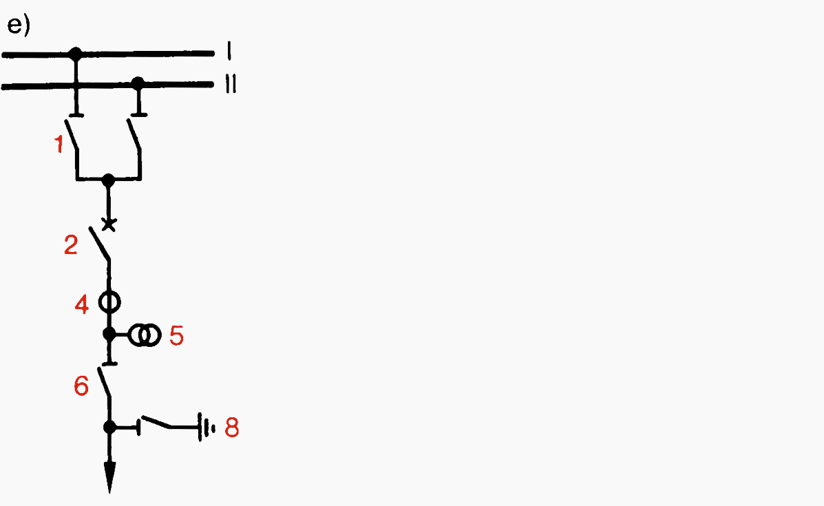
3b. Connections of instrument transformers – Variations e) to g)
e) Normal branches
The instrument transformers are usually placed beyond the circuit-breaker 2, with voltage transformer 5 after current transformer 4. This is the correct arrangement for synchronizing purposes.
Some kinds of operation require the voltage transformer beyond the branch disconnectors, direct on the cable or overhead line.
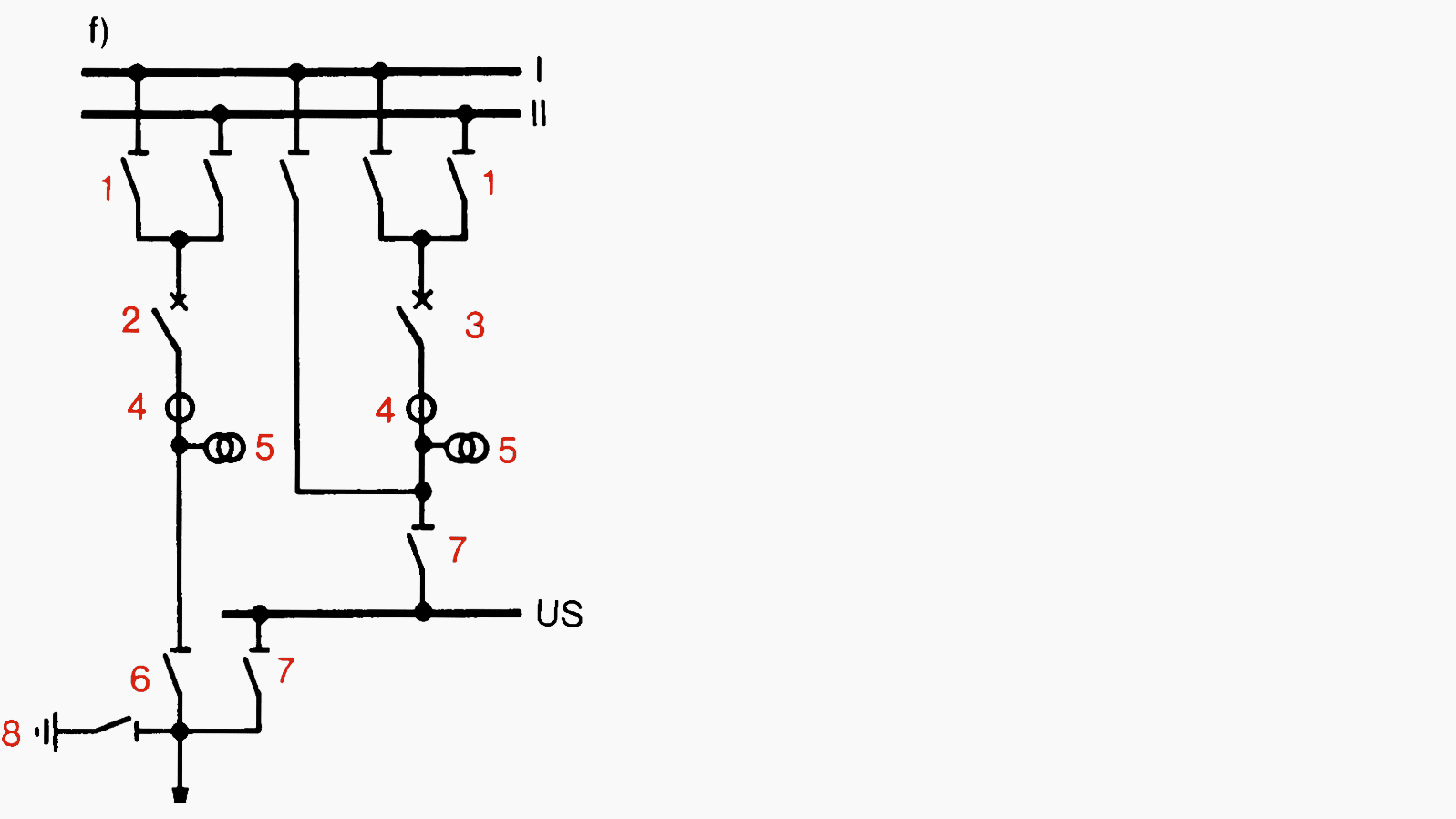
f) Station with bypass busbar
Instrument transformers within branch.
The instrument transformers cease to function when the bypass is in operation. Line protection of the branch must be provided by the instrument transformers and protection relays of the bypass. This is possible only if the ratios of all transformers in all branches are approximately equal.
If capacitive voltage transformers are used which also act as coupling capacitors for a high-frequency telephone link, this link is similarly inoperative in the bypass mode.
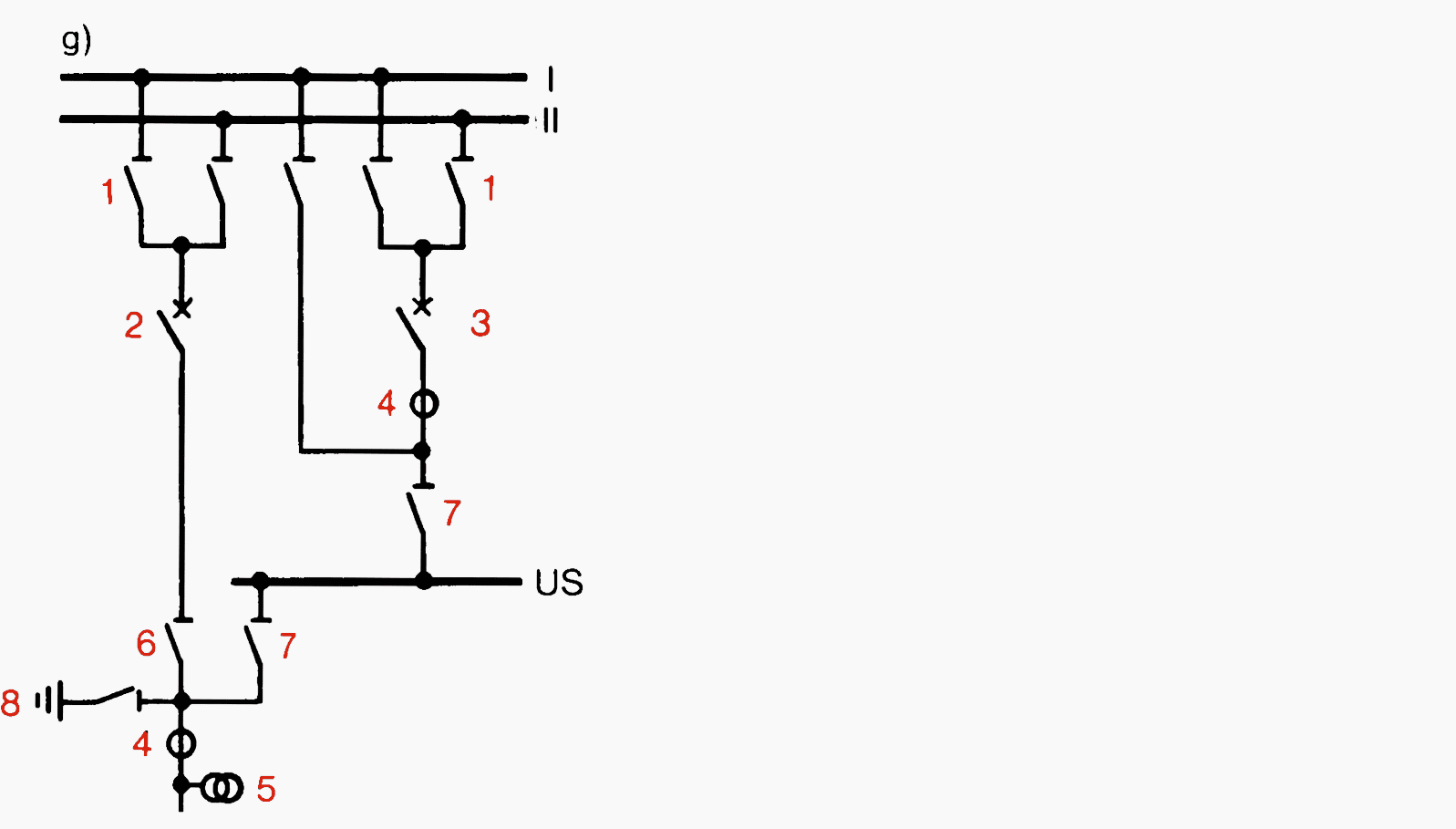
g) Station with bypass busbar
Instrument transformers outside branch.
In bypass operation, the branch protection relays continue to function, as does the telephone link if capacitive voltage transformers are used. It is only necessary to switch the relay tripping circuit to the bypass circuit-breaker 3.
The decision as to whether the instrument transformers should be inside or outside the branch depends on the branch currents, the protection relays, the possibility of maintenance and, in the case of capacitive voltage transformers, on the h.f. telephone link.
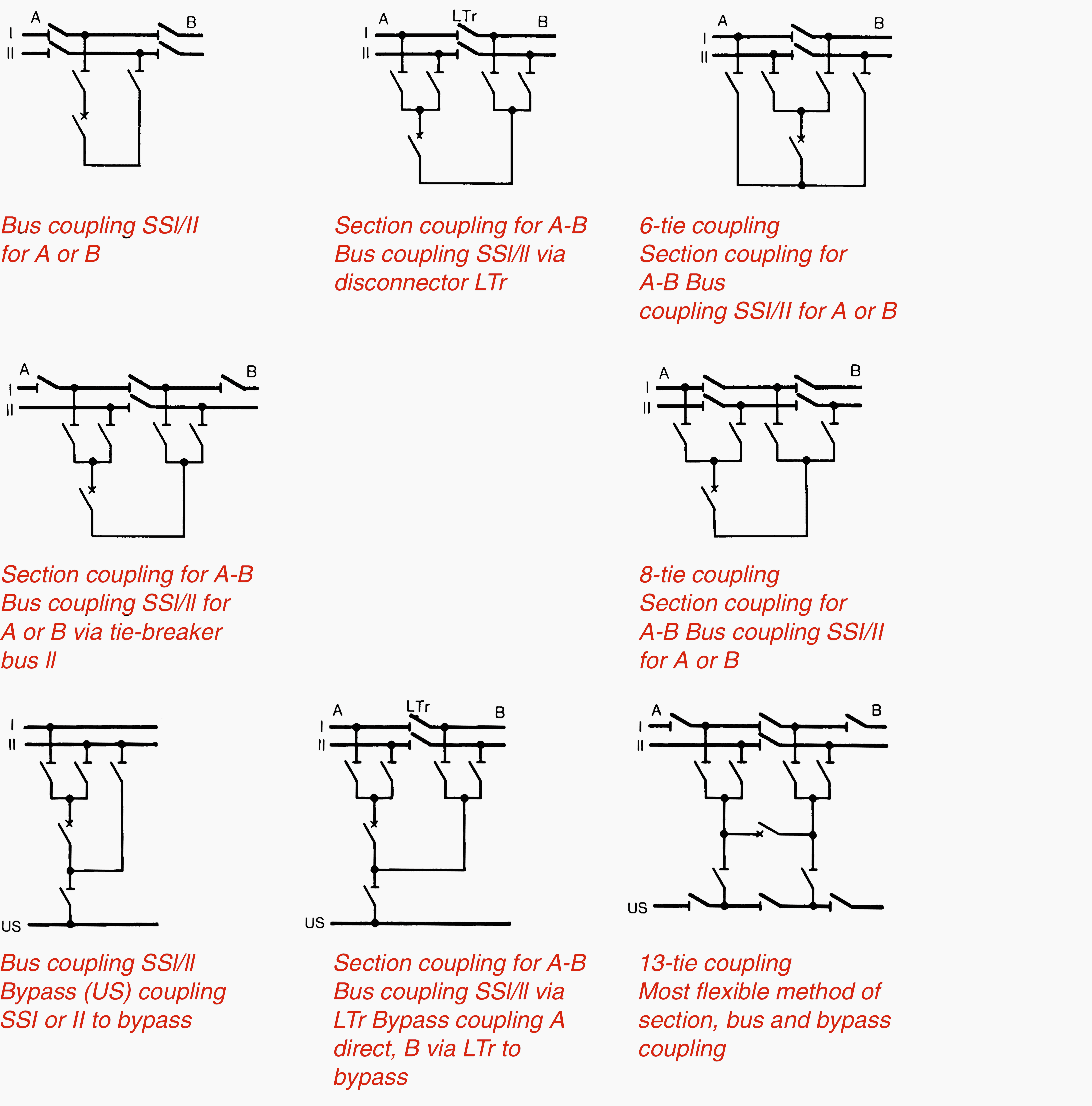
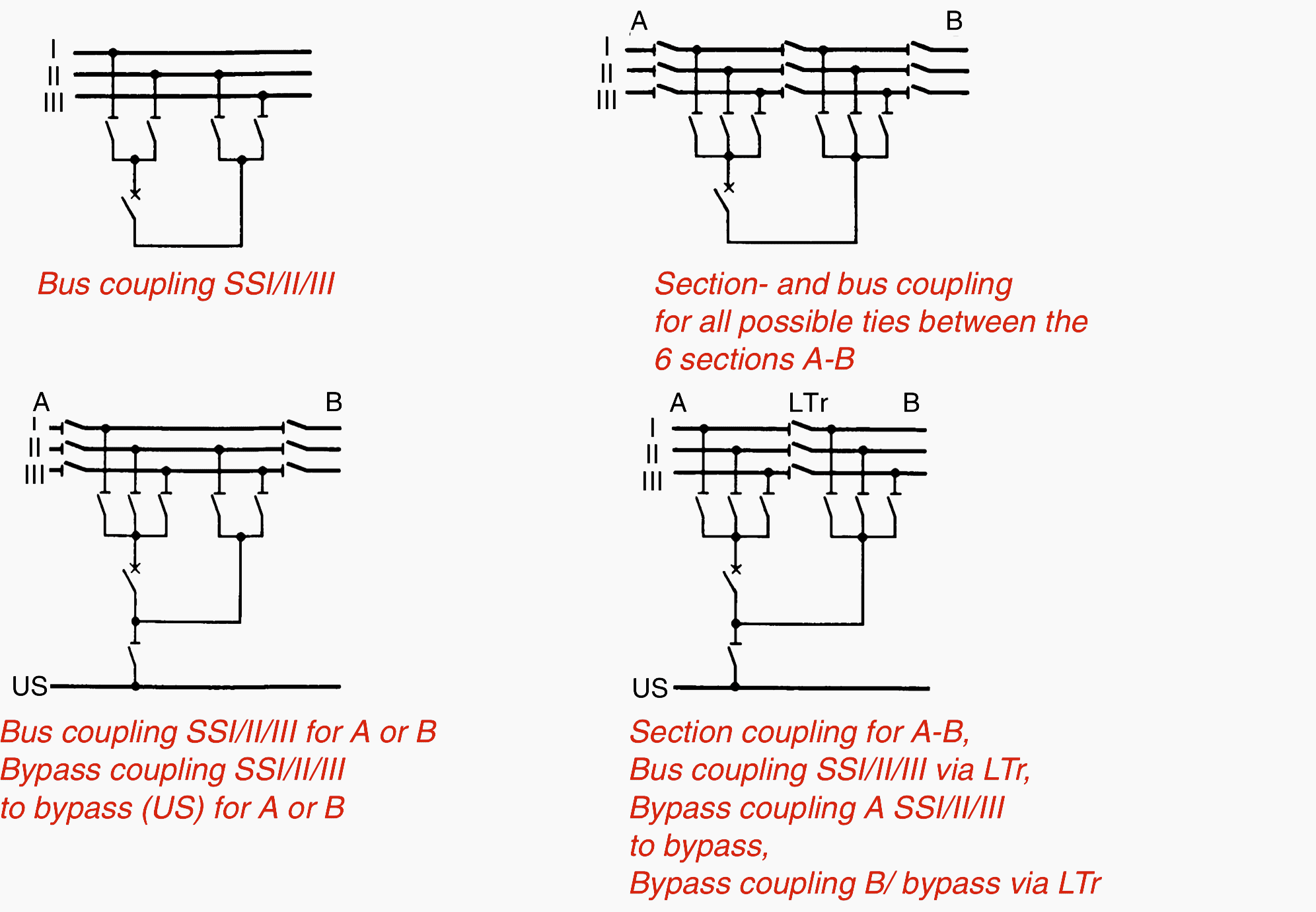
3c. Busbar coupling connections
Experience shows that more complex coupling arrangements are usually needed in order to meet practical requirements concerning security of supply and the necessary flexibility when switching over or disconnecting.
Division into two bays is generally required in order to accommodate the equipment for these tie-breaker branches.
Double busbars
Triple busbars
Reference // ABB Switchgear Manual
Related electrical guides & articles


Edvard Csanyi
Hi, I'm an electrical engineer, programmer and founder of EEP - Electrical Engineering Portal. I worked twelve years at Schneider Electric in the position of technical support for low- and medium-voltage projects and the design of busbar trunking systems.I'm highly specialized in the design of LV/MV switchgear and low-voltage, high-power busbar trunking (<6300A) in substations, commercial buildings and industry facilities. I'm also a professional in AutoCAD programming.
Profile: Edvard Csanyi

Hi Edvard,
Thanks for this excellent comprehensive article! I am interested in substation configurations commonly used in Canada at MV and HV level. Typically, different countries favor certain designs. Do you know where I can get information on that?
thanks
Graham
Amazing
Junior electrical engineer. Thanks for your wonderful insights; i really want to learn more.
I am engineer electrical and now working in algeria
Dear sir Edvard,
Congratulation! I am a candidate to take Professional Electrical Engineer in the Philippines.and practicing
EE profession Thanks for all the technical references from EEP..your advocacy to help Electrical Engineers and Electrical Engineering Students around the world is a great treasure and as current president of Institute of Electrical Engineers of the Philippines Inc. (IIEE) Southern Laguna Chapter, we would like to recognize your goodwill by sending you a Certificate of Recognition from our chapter..Again, Congratulation sir Edvard!
Very insightful. I am responsible for secondary substation maintenance. South Africa
Thank you Maditsela.
Dear sir,
I am your EEP Friend. I am Electrical Engineer, Now working in Iraq,Bismayha New City Project, Bagad. I am Bangladeshi.
Thanks for your useful Post .Your post is very helpful for electrical engineer.