
Estimated Study Time: 14 minutes
Switchgear design installations
What is the civil engineering of substation? The civil engineering includes a large quantity of information and details for the structural drawings required to design switchgear installations. The structural drawings are the basis for producing the structural design plans (foundation, shell and reinforcement plans, equipment plans).
 Civil engineering in installation of substation buildings and switchboard rooms
The structural information includes the following data:
- Spatial configuration of the installation components
- Aisle widths for control, transport and assembly
- Main dimensions of the station components
- Load specifications
- Doors, gates, windows with type of opening and type of fire-preventive or fire-resistant design
- Ceiling and wall openings for cables, pipes or conduits
- Information on compartments with special equipment
- Information on building services
- Ventilation, air-conditioning information
- Floors including steel base frames
- Foundation and building earth switches
- Lightning protection
- Drainage
- Fire protection.
The following design details must be observed for indoor substation buildings and switchboard rooms.
- General about indoor substation buildings and switchboard rooms
- Ventilation
- Fire Rating
- Earthing
- SF6 installations
- Pressure relief
- Cable laying
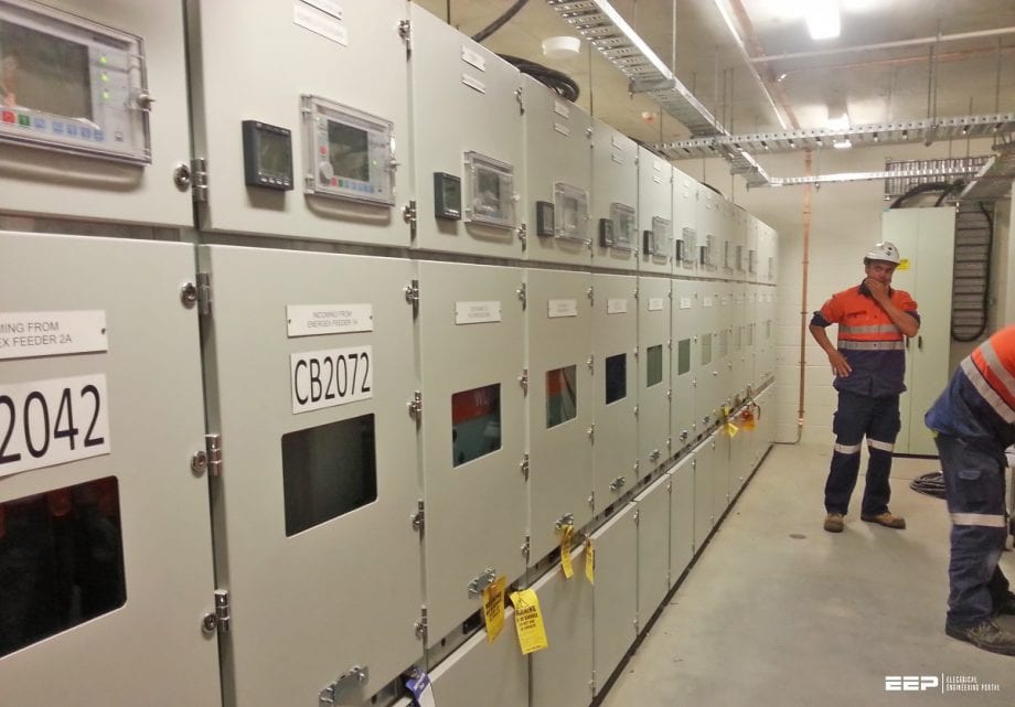
Indoor substation buildings & switchboard rooms
1. General
When planning indoor installations of substation buildings and switchboard rooms, in addition to configuration to meet operational requirements, ensure that the selected rooms are not affected by groundwater and flooding and are also easily accessible for control and transport equipment and also for fire fighting.
The current applicable construction codes, regulations and directives must be observed. Construction laws include regulations that must be observed and in addition, the generally accepted engineering requirements apply. Walls, ceilings and floors must be dry. Pipes carrying liquids, steam and flammable gases must not be laid in, above a under rooms intended for switchgear installations.
The exits must be located so that the escape route from the installation is no more than 40 m for rated voltages over 52 kV and no more than 20 m for rated voltages of up to 52 kV. A service aisle more than 10 m long must have two exits, one of which may be an emergency exit.
The interiors of the switchgear house walls must be as smooth as possible to prevent dust from accumulating. The brickwork must be plastered, but not the ceilings in the area of open installations, so switchgear parts are not subject to falling plaster.
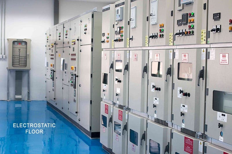
The floor covering must be easy to clean, pressure-resistant, non-slippery and abrasion-proof (e.g. stoneware tiles, plastic covering, gravel set in concrete with abrasion-resistant protective coating to reduce dust formation). The pressure load on the floor from transport of station components must be considered
The electrostatic properties of the floor covering are of importance in rooms with electronic devices. Steps or sloping floor areas must always be avoided in switchgear compartments.
This condition is considered to be met by one of the following measures:
- The window consists of unbreakable materials.
- The window is barred.
- The bottom edge of the window is at least 1.8 m above the access level.
- The building is surrounded by a fence at least 1.8 m high.
2. Ventilation
The rooms should be ventilated sufficiently to prevent the formation of condensation. To prevent corrosion and reduction of the creepage distance by high humidity and condensation, it is recommended that the typical values for climatic conditions listed in IEC 62271-1 be observed in switchgear rooms.
The following apply:
- The maximum relative humidity is 95 % in the 24 hour average,
- The highest and lowest ambient temperature in the 24 hour average is 35 °C and
- -5 °C with “Minus S Indoor” class.
In areas of high pollution, the compartments must be kept at a low level of overpressure with filtered air. The air vents required for this must be protected against rain, spray water and small animals. Prod-proof plates must also be installed behind the vents below heights of about 2.50 m above ground.
See this technical article for additional information on ventilation.
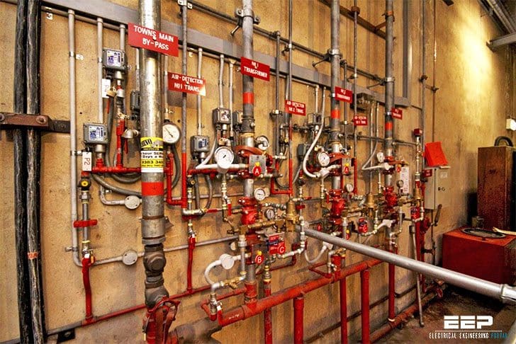
3. Fire Rating
A fire in the substation MUST not put people at an unacceptable risk. These risks include the spread of fire, smoke, and interference with means of escape from fire and smoke.
Substations must be located so that doors open onto low-fire risk outside areas.
The substation should be constructed with the internal leaf of block on flat, poured concrete floor and roof slab. All ducts, both above and below ground level, should be sealed by the builder (or developer responsible for the building project) to provide a four-hour fire rating.
All substations incorporated into larger buildings must have a smoke detector fitted to the door. The detector shall be connected to the fire alarm system in the main building. A customer may, at their discretion, fit a smoke detector to the door of a free standing MV substation on their property.
4. Earthing
Earthing of an MV substation is extremely important. It reduces the possibility of stray voltages around the substation. It helps to protect operating staff and members of the public from electric shock.
There are three main elements that have to be installed during the substation construction:
- Earthed steel reinforcing mesh in the substation floor.
- Copper earth wires laid as required adjacent to the substation.
- A copper earth mat under the footpath at the substation door.
For more information, please refer to the following guide:
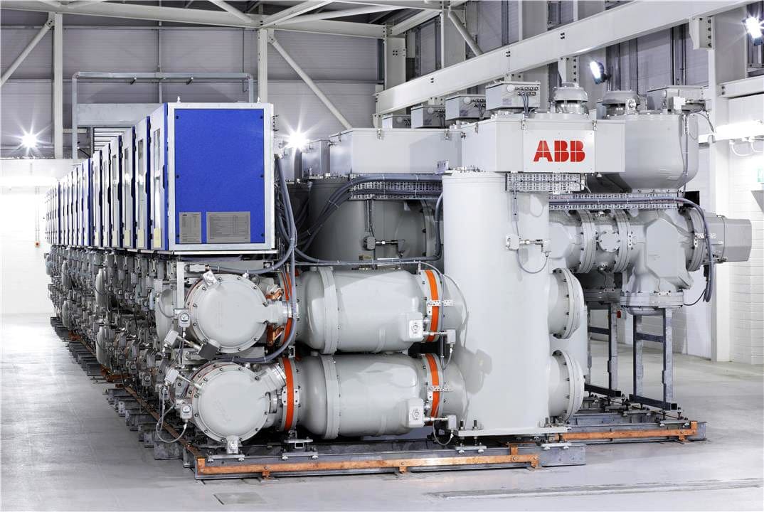
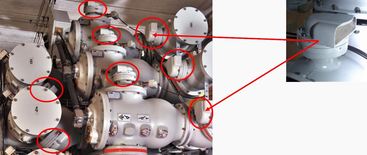
5. SF6 installations
For SF6 installations, it is recommended that the building be extended by the length of one bay for installation and renovation purposes and that a hoist system with a lifting capacity equal to the heaviest installation components be installed.
Mechanical ventilation is not necessary so long as the gas content of the largest contiguous gas space including the content of all connected SF6 tanks (based on atmospheric pressure) does not exceed 10% of the volume of the compartment receiving the leakage gas.
Mechanical ventilation may be required in the event of faults with arcing.
6. Pressure relief
In the event of an accidental internal arc in a switchgear installation, significant overpressure occurs in switchgear compartments, in particular in those with conventional air insulation with high arc lengths. Damage to walls and ceilings caused by unacceptably high pressure load can be prevented by appropriate pressure relief vents. Floor plates must be properly secured.
Pressure relief facilities in switchgear rooms should meet the following criteria:
- They should normally be closed to prevent the entry of small animals, snow, rain etc.; light, self-actuating opening of the facility at an overpressure of less then 10 mbar;
- Pressure relief in en area where there are usually no personnel;
- No parts should become detached during pressure relief.
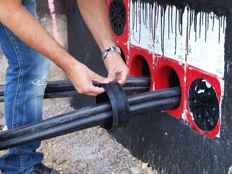
7. Cable laying
The options listed below are available for cable laying: Tubes or cable conduit forms, covered cable conduits, cable conduits accessible as crawl space, cable floors and accessible cable levels. Tubes or cable conduit farms are used to lay single cables. To avoid water damage when laid outside they should be sloped.
The bending radius of the cable used should be observed for proper cable layout. Covered cable conduits are intended when several cables are laid together, with the width and depth of the conduit depending on the number of cables.
The conduits should be placed before the compartments to allow cable work to be done at any time without having to disconnect equipment.
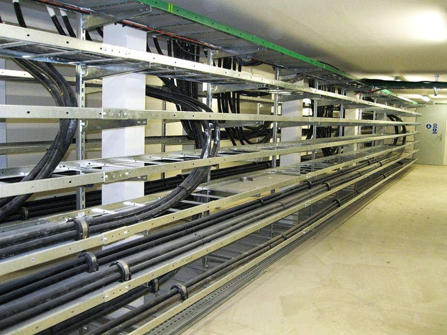
Cable conduits accessible as crawl spaces and cable floors should be at least 1.50 m wide; the overhead clearance should not be less then 1.00 m to allow for any cable crossings. Access and ventilation openings and the required cable accesses must be taken into account. Accessible cable conduits and cable levels are required for a large accumulation of cables in larger installations.
A height of 2.10 m (to the lower edge of the support girder) is recommended to provide space for the required lighting and suspended cables. The cables can be laid on cable racks and also fastened to supports using cable clamps. Escape paths (emergency exits) must be available.
Access doors must open outwards, should be airtight when closed, must be fire-resistant and have a panic lock. Auxiliary cables are laid on separate cable racks or on supports beneath the ceiling.
Separate conduits should be provided for cable laying where possible. The cable conduits, particularly for the power cables, must be dimensioned to provide sufficient space for the heat from power dissipation.
References:
- ABB Book
- Safety and availability in GIS by Jessica Ponce de Leon (ABB)
- Construction Standards for MV Substation Buildings by ESB Networks
Related electrical guides & articles


Edvard Csanyi
Hi, I'm an electrical engineer, programmer and founder of EEP - Electrical Engineering Portal. I worked twelve years at Schneider Electric in the position of technical support for low- and medium-voltage projects and the design of busbar trunking systems.I'm highly specialized in the design of LV/MV switchgear and low-voltage, high-power busbar trunking (<6300A) in substations, commercial buildings and industry facilities. I'm also a professional in AutoCAD programming.
Profile: Edvard Csanyi

much thanks and i appreciate your efforts
for to much learn.
and one question is it way to connected the reinforcement concrete bars RC with the Earthing network in GIS substation building
Very useful information. Just in time for designing our substation.
i am sr consultant of electrical EPC contractors especially 33/11 kv sub station and line work
This is a very important information for all power engineers
Thank you for the informative and useful articles.
Good article. Some more structural inputs required
I want to study