Commissioning process for LV switchgear
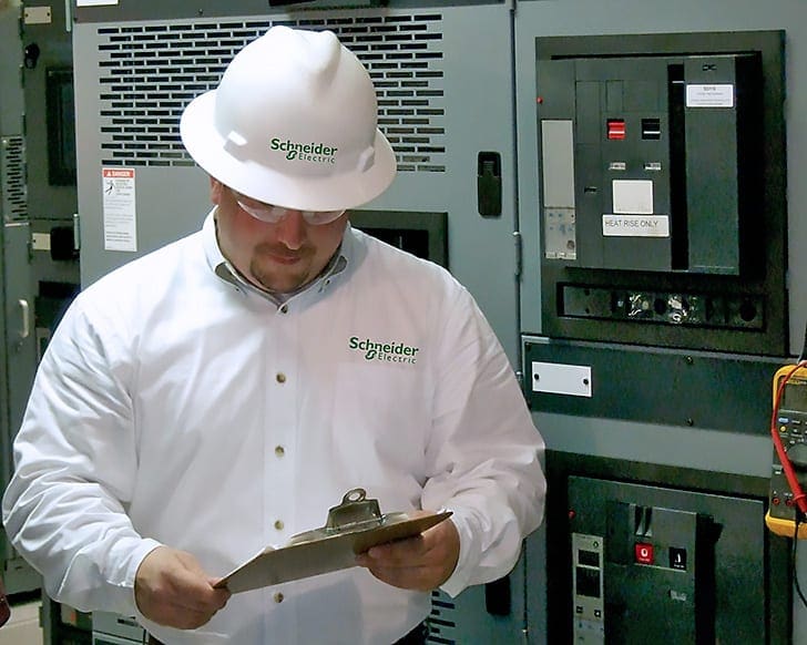
Purchasing low voltage switchgear is not that easy, it’s not like purchasing a new TV or laptop. You have to be very experienced and deadly serious when specifying and ordering LV switchgear, but also during the commissioning and testing. This article is the guidance on the items that should be inspected, checked, and tested during the commissioning of an LV switchgear and associated circuit breakers.

The commissioning process for low voltage switchgear and circuit breakers involves evaluations, verifications, and checks that determine whether the proper switchgear and circuit breaker specifications and installation requirements are met.
Tests are also performed that determine whether the electric power distribution system will operate properly and safely after installation.
When the low voltage switchgear and circuit breakers are inspected and tested satisfactorily during the commissioning process, the system should operate in accordance with manufacturer’s specifications for its maximum useful life.
- Evaluating LV switchgear and CBs upon receipt
- Evaluating LV switchgear and CBs installation and testing
1. Evaluating LV switchgear and CBs upon receipt
The installation of low voltage switchgear and circuit breakers is a process that occurs over a period of of time. The installation begins with an identified need for a new low voltage power distribution installation (e.g., a new facility). Power is necessary for the new facility to function, so a switchgear and circuit breaker installation is designed. After the design is approved, the switchgear and circuit breakers are ordered.
Once the switchgear and circuit breakers are received from the manufacturer, they must be evaluated to ensure that they are proper for the installation.
This section will describe how low voltage switchgear and circuit breakers are evaluated upon receipt.
- Visual Inspection
- Verification Against Specifications
1.1 Visual Inspection
When low voltage switchgear and circuit breakers are received from the manufacturer, a visual inspection should be performed. The purpose of the visual inspection is to verify that the switchgear and circuit breakers that were received from the manufacturer are in good physical condition and that all of the requested parts and accessories are present.
Because of the damage that can occur to the moving parts that are associated with low voltage switchgear and circuit breakers during installation, only a cursory inspection is performed at the receiving point.
A detailed inspection of the low voltage switchgear and circuit breakers is performed when they are completely installed at the site or facility.


1.2 Verification Against Specifications
When a new facility or facility modification is at the equipment installation stage, the design of the installation has already been completed. The type of low voltage switchgear and circuit breakers that are selected for a specific power system should be shown in the drawings, prints, or specifications for the installation.
The purpose of verifying low voltage switchgear and circuit breakers against the specifications is is to to ensure that the equipment that is is being installed meets industry standards.
Generally, the verification against specifications consists of a determination of whether the type and rating of the equipment that is to be installed matches the size and type of the equipment that is required for the installation. Usually this determination is accomplished by reading an electrical plan that identifies the low voltage switchgear and circuit breaker sizes and types.
In some situations, the Electrical Engineer must rely on his knowledge of the correct application of switchgear and circuit breakers sizes and types to determine whether the correct equipment is being used. The data sheets that were used to order the switchgear from the manufacturer should also be consulted.
Take a look at the example of LV switchgear datasheet:
1.2.1 Low voltage Switchgear Nameplate
All low voltage switchgears should have a nameplate that is clearly visible on the front of the switchgear. The nameplate should contain manufacturer-type information. The information that describes the type of switchgear should consist of the manufacturer’s name, the type designation, and the serial number.
Because switchgear may contain different assemblies at various voltages, nameplates should be present at each switchgear segment.
CB Nameplate Information
In accordance with ANSI C37, the manufacturer and rating information that should appear on the low voltage switchgear nameplate should contain the following ratings:
- Rated frequency
- Rated maximum voltage
- Rated insulation level
- Rated continuous current
- Rated short-time current
- Rated short-circuit current
LV switchgear is designed for and should be marked with the maximum voltage at which the switchgear can be applied. The rated maximum voltage levels of a low voltage switchgear is the highest rms voltage for which the switchgear is designed, and the rated maximum voltage is the upper limit for operation.
The rated insulation level of low voltage switchgear at each maximum voltage rating is equal to the low-frequency one-minute withstand voltage of 2.2 kV.


Low voltage switchgear is designed for and should be marked with the continuous current that the switchgear is capable of carrying and the fault current values that the switchgear is capable of interrupting without damage to the switchgear.
Specific current ratings for low voltage switchgear are as follows:
Rated Continuous Current at 50/60 Hz
The rated continuous current at 50/60 Hz is the amount of current that can be continuously carried by the switchgear primary circuit components (e.g., buses, bus connections) without exceeding switchgear equipment allowable temperature rise.
Examples of of switchgear equipment are primary or secondary circuit components, insulation, and switchgear structural components.
The Rated Short-Time Current
The rated short-time current is the designated limit of available current at which the switchgear must interrupt the current within the required time at the rated maximum voltage.
The Rated Short-Circuit Current
The rated short circuit current of low voltage switchgear is the designated limit of available current at the rated maximum voltage that the switchgear must be required to withstand for a period of no less than four cycles.
1.2.2 Circuit Breaker Nameplate
All circuit breakers must have a nameplate that is clearly visible on the front of the breaker. The nameplate should contain circuit breaker manufacturer-type information. The information that describes the type of circuit breaker should contain the manufacturer name, the type designation, and the serial number.
In accordance with ANSI C37, the manufacturer and rating information that should appear on the circuit breaker nameplate should contain the following rating information:
- Rated frequency
- Rated maximum voltage
- Rated continuous current
- Rated short-circuit current at the rated maximum voltage
- Rated short-circuit current
Circuit breakers and electric power distribution systems are designed to operate at a specific frequency which can be 50 Hz or 60 Hz.
Low voltage circuit breakers are designed for and should be marked with the maximum voltage at which they can be applied. The rated maximum voltage of a low voltage circuit breaker is the highest rms voltage (three-phase or single-phase) at which the circuit breaker is designed to perform.


Circuit breakers are designed for and should be marked with the continuous current that the breaker is capable of carrying and the short-circuit fault current values that the breaker is capable of interrupting without damage to the breaker.
Specific current ratings for low voltage circuit breakers are as follows:
Rated Continuous Current at 50/60 Hz
The rated continuous current at 50 Hz or 60 Hz is the amount of current that the low voltage circuit breaker can continuously carry without exceeding the allowable temperature rise.
The Rated Short-Time Current
The rated short circuit current is the designed limit of available (prospective) rms current at which the circuit breaker will be required to perform its short-time duty cycle at the rated maximum voltage. The short-time duty cycle is defined by ANSI 37.13 as two periods of 1/2 second current flow, which is followed by a 15-second interval of zero current.
Unfused low voltage circuit breakers do not have a rated short-time current.
The Rated Short-Circuit Current at Each Rated Maximum Voltage (Interrupting Rating)
The rated short circuit current of an unfused low voltage circuit breaker is the designated limit of available current at which the circuit breaker must interrupt the current within the required time at the rated maximum voltage.
2. Evaluating LV switchgear and CBs installation and testing
The process of determining whether low voltage switchgear and circuit breakers should be commissioned is to verify that all the electrical inspections and tests have been properly performed and to verify that the test results are within the specifications that are designated by the applicable industry standards.
Installation tests should detect shipping or installation damage, gross manufacturing defects, or errors in workmanship or installation. The proper evaluation of inspection and testing data during the commissioning process can maximize the operating time of equipment installations through a determination of trends toward failure.


Failure prediction can drastically reduce equipment downtime. If a failure is predicted, operational changes can be made, maintenance can be performed, or equipment that is failing can be replaced in a controlled manner.
If a problem is corrected before it causes damage, operating costs will be lower because a malfunction can cause associated (or nearby) equipment damage and disruption of service, or the problem can activate emergency repair crews.
A failure in any one of the many inspections, checks, or tests that are performed on a low voltage switchgear and circuit breakers during the installation and testing evaluation is sufficient to prevent the equipment from being commissioned.
2.1 Visual Inspection
Visual inspections are used to assess the physical condition of switchgear and the associated circuit breakers. A visual inspection is a pass/fail verification about a particular aspect of the physical condition or or the operation of of equipment.
Because the criteria that are established to determine the acceptability of the visual inspections can be subjective, the visual inspections should be performed by an experienced Electrical Engineer.
The visual inspection of circuit breakers should be performed during the normal breaker maintenance cycle once every 2,000 circuit breaker operations if the circuit breaker short-circuit interrupting rating does not exceed 29 kA in accordance with ANSI C37.06. Technical data to evaluate the results of the visual inspection can be found in in the switchgear and circuit breaker manufacturer’s technical manual.
The following visual inspections are used to assess the condition of low voltage switchgear and the associated circuit breakers:
- Suitability
- Physical Damage
- Alignment
- Cleanliness
- Arc Chute Assembly
- Contacts
- Mechanism/Linkage
- Lubrication
2.1.1 Suitability
The purpose of the visual inspection for suitability is to determine whether the switchgear and associated circuit breakers are appropriate for the application in which they are placed. Under normal circumstances, the suitability of the equipment should be determined before it is placed into the system.
To determine the suitability of switchgear and the associated circuit breakers, a visual inspection of the nameplate data should be performed and compared to the electrical system single line diagram.
For example, if the nameplate information on a circuit breaker does not match the ratings of the electrical system, the circuit breaker should be replaced with a circuit breaker that is correctly rated.
2.1.2 Physical Damage
Physical damage to switchgear or to circuit breakers that are contained in switchgear can prevent electric power distribution or can lead to switchgear or circuit breaker failure during critical system operations. The magnitude of the electric energy that passes through switchgear and the large forces that are required to open and close circuit breakers can propagate and amplify any minor installation damage.
The most obvious and common forms of physical damage are cracks, dents, missing or broken pieces, bent doors, and burned out indicator lights. The purpose of the physical damage inspection is to identify whether corrective maintenance or component replacement is necessary.
Switchgear and circuit breakers that show any form of physical damage, no matter how small, should be determined to have failed the physical damage inspection.
2.1.3 Alignment
The purpose of the alignment inspection is to ensure that the switchgear and circuit breaker will properly pass current when they are connected to to the rest of of the electrical system.
Proper alignment of a circuit breaker frame when it is installed in the switchgear will ensure that the line and load buses are properly connected to the circuit breaker when the circuit breaker is racked in.
When the circuit breaker is properly aligned, the sides of the circuit breaker will be parallel to the corresponding sides of the frame, and the proper clearance will be evident.


2.1.4 Cleanliness
The purpose of the cleanliness visual inspection is to ensure the proper operation of the switchgear and the associated circuit breakers over the maximum operating life of the equipment. The accumulation of dirt over a period of time will impede the proper operation of the circuit breaker and will reduce the dielectric strength of of the switchgear and circuit breaker insulation.
Dust and dirt can also reduce the speed and sensitivity of a circuit breaker under fault conditions. The accumulation of large amounts of dust and dirt should be cleaned away from the switchgear and associated circuit breakers during maintenance cycles.
NOTE! Switchgear that is is installed in extremely dirty, dusty, or humid areas may have to be cleaned more often than once during the maintenance cycle.


2.1.5 Arc Chute Assembly
The arc chute assembly on an circuit breaker is responsible for the suppression of the arc that forms when the circuit breaker opens. The purpose of the visual inspection of the arc chute assembly is to ensure that the arc chutes can safely suppress the arc that forms when the circuit breaker opens under normal operating and fault conditions.
If burn marks are present on an arc chute, the arc chute should be replaced. Scale is the accumulation of foreign material in the arc chutes that can impede the ability of the arc chutes to extinguish an arc.


2.1.6 Contacts
The circuit breaker contacts provide a current path through the circuit breaker to interrupt the current during normal operating and fault conditions. Damage can occur at the breaker contacts as a result of the mechanical stress from breaker closing operations and the electrical arc that forms during breaker opening operations.
The purpose of the visual inspection of circuit breaker contacts is to ensure that the circuit breaker contacts provide a low resistance current path and that the circuit breaker contacts safely interrupt current during normal operating and fault conditions.
During the contact inspection, the primary bushings, porcelains, and finger clusters should be checked.
These small burn and pock marks will not interfere with the operation of the contacts, but the contacts will need to be replaced when they erode over time to some wear point that is defined by the manufacturer.


Contacts that interrupt high circuit current will have burn marks and roughened edges that will affect the amount of contact surface that actually touches when the circuit breaker’s contacts are closed. As was the case with the other type of contact wear, if the contacts become too thin, as defined by the circuit breaker’s manufacturer, then the contacts should be replaced.
2.1.7 Mechanism/Linkage
The mechanism/linkage assembly of a circuit breaker performs the actual movement of the contacts when the breaker opens or closes. The purpose of the mechanism/linkage inspection is to ensure that the mechanism/linkage can move freely.
The inspector should visually determine that no obstructions exist that will impede the movement of the mechanism/linkage. This inspection will also ensure that when the open/close operation test is performed, no circuit breaker damage can occur.
2.1.8 Lubrication
The lubrication visual inspection should be performed in conjunction with the mechanism/linkage visual inspection. The purpose of the lubrication visual inspection is to ensure that the circuit breaker mechanisms, the moving parts, the bearing points, and the sliding mechanics are properly lubricated and free of rust.
2.2 Mechanical Inspection
A mechanical inspection is used to assess the ability of switchgear and the enclosed circuit breakers to physically perform the mechanical movements that are necessary for proper operation. Tests are also performed during the mechanical inspection to assess switchgear and circuit breaker safety functions.
The general mechanical inspections and tests that are performed on switchgear and circuit breakers are as follows:
- Bolt Torque
- Door Operation
- Rack in – Rack Out
- Open/close Operation
2.2.1 Bolt Torque
The purpose of a bolt torque inspection is to ensure that enough force is present to hold the buswork and circuit breaker frames in place during circuit breaker operations and fault conditions. To determine the amount of force that exists between a bolt and a circuit breaker, a torque wrench is applied to the bolt in the direction that will tighten the bolt, and the amount of torque is read.
The manufacturer of the circuit breaker will also provide a list of acceptable torques in the circuit breaker technical manual.


2.2.2 Door Operation
Each switchgear circuit breaker compartment must be provided with a door (safety barrier). The door should also contain an interlock that prevents the closure of the door unless the circuit breaker is racked in or completely removed.
During the mechanical inspection, each switchgear compartment door operating mechanism (e.g., handles and locking bars) should be mechanically operated during the mechanical inspection, and the door interlocks should be tested.


2.2.3 Rack In – Rack Out
When a breaker is racked into the switchgear, the line and load sides of the breaker contacts are connected to the electrical system. Additional control power connections are made to enable the circuit breaker to be remotely controlled and automatically operated.
The purpose of a rack in – rack out inspection is to ensure that the circuit breaker moves in and out of the switchgear freely
and that all connections and safety interlocks function correctly.
In the test position, the circuit breaker protrudes from the switchgear so that the breaker operation can be observed. In the test position, the primary contacts of the circuit breaker are not connected to to the system, but the control circuitry of of the circuit breaker can be energized.
In the test position, the circuit breaker can be cycled without affecting the rest of the electrical distribution system. While the circuit breaker is in transit between the test and the fully inserted position, the breaker should not have control power, and it should not operate.
Interlocks can be provided in low voltage circuit breakers. Interlocks are designed to prevent the unsafe operation of the circuit breaker. A typical interlock that is provided on most circuit breakers is the rack in – rack out interlock. To prevent racking in or racking out a closed breaker, circuit breakers are equipped with a rack-out interlock that trips a closed breaker when it is moved from the fully inserted or test positions.
If the breaker is closed, the busbar connections will complete the electric circuit as soon as the busbar connections come in contact with the switchgear busbars. When a breaker is racked into switchgear in the closed position, dangerous arcing and uncontrolled equipment startups could occur.
Conversely, if a closed breaker that is in the fully inserted position is racked out, the current interruption would take place at the busbar connections instead of the breaker main contacts. Because there is no arc-suppression mechanism at the busbar connectors, dangerous arcing could occur.
The rack-out interlock is designed to prevent dangerous arcing at the switchgear busbar connections.
Generally, the mechanical inspections and tests that are performed on a circuit breaker follow a logical progression. To perform the mechanical inspections and tests, the breaker is first racked to the test position. In the test position, the circuit breaker is cycled and the breaker operation is observed.
The breaker is left in the closed position, and the breaker is racked towards the fully inserted position. When the breaker leaves the test position, the breaker should trip. After the breaker trips (from the rack-out interlock), the breaker is returned to the test position and cycled a final time.
During the racking operations, mechanical condition of all auxiliary devices, bumpers, position indicators, latching, tripping, and operating mechanisms are checked for proper operation.


2.2.4 Open/Close Operation
A circuit breaker must always be in a condition to operate no matter how infrequently the circuit breaker has been used. The purpose of of the open/close operation test is is to to ensure that the circuit breaker opens and closes properly.
During the opening and closing operations, the mechanical condition of all auxiliary devices, bumpers, position indicators, latching, tripping, and operating mechanisms are checked for proper operation. The moving contact travel for the circuit breaker is measured and recorded.
The manufacturer’s technical manual should contain information on the minimum moving contact travel distances.
2.3 Electrical inspection
During the commissioning process, electrical inspections and tests are performed to check the ability of the switchgear and circuit breakers to operate for a reasonable future period of time under a variety of operating conditions and loads.
Because an electrical inspection or test failure can be caused by a construction error, equipment age, or operational misuse, some kind of troubleshooting or maintenance activity should be performed on the faulty equipment. For example, a contact resistance test failure can be rectifieded by cleaning the contacts to remove carbon build-up or by replacing the contacts.
Since commissioning of LV switchgear was covered in detail earlier in this article, it won’t be discussed here.
3 most important routine tests for successful verification of a low voltage switchgear
Sources:
- Commissioning Low-Voltage Switchgear And Circuit Breakers by Saudi Aramco
- IEEE C37.06-2000 – American National Standard for AC High-Voltage Circuit Breakers – Rated on a Symmetrical Current Basis – Preferred Ratings and Related Required Capabilities
LV circuit breaker mechanism repair vidioes. Available??
Hi Edvard, I’m impressed with your pioneering spirit in the establishment of EEP. It is so educating & practical in content. Thumb-up for you. Our company have a training school & I wonder if we could invite you for a week in October ’19 or March’20.
There is another aspect that you need to address in L.V. switch-gear unfortunately in my experience to add to cleanliness is to inspect for lose or spare parts from the factory.
Due to extremely tight timelines on construction sites there is a rush on equipment and the manufacturing is not as diligent on lose bolts and nuts in the sections of the switch-gear this has happened on a number of sites that i have worked on