
Estimated Study Time: 10 minutes
Numerical protection
Numerical protection is based on a number of microprocessors that can be programmed to reproduce virtually any type of protection and relay. It represents important advantages in reliability, space and economics compared to conventional protection arrangements.
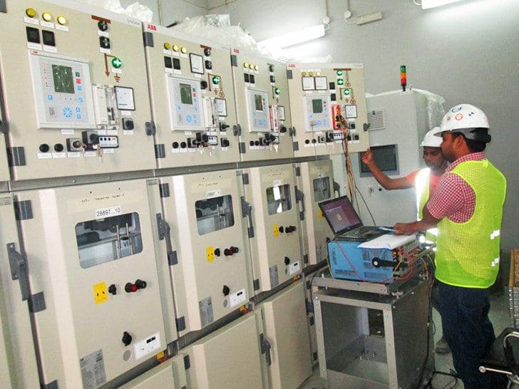
 Commissioning Numerical Protection and Procedure For Carrying Out Performance Tests (photo credit: omicronenergy.com)
The method of calculating settings on numerical protection does not differ greatly from that used for conventional protection. However, there are big differences in the procedures to be followed during testing and commissioning this type of protection.
When numerical protection is used, most of the wiring of a traditional relay arrangement is substituted by the programmable logic, with the great advantage of having multiple configurations and settings available as the numerical protection permits it.
Consequently, programmable logic should be included along with all settings in the documentation for construction, commissioning and testing purposes.
Setting the parameters
The method of setting numerical protection differs considerably from that used for electromechanical relays. Setting the parameters of a numerical protection, also known as parameterisation, involves selecting the functions of system configuration, protection, control, communication, alarms and reporting features.
Parameter settings are achieved by carrying out the following operations:
- Selecting the required power system configuration and parameters of general operation;
- Selecting the required protection functions;
- Determining the setting groups;
- Determining the dynamic or adaptive schemes;
- Determining the relay logic and number of digital inputs and outputs;
- Determining the configuration of reporting features and alarms.
Figure 1 represents the set-up system summary in a numerical protection.
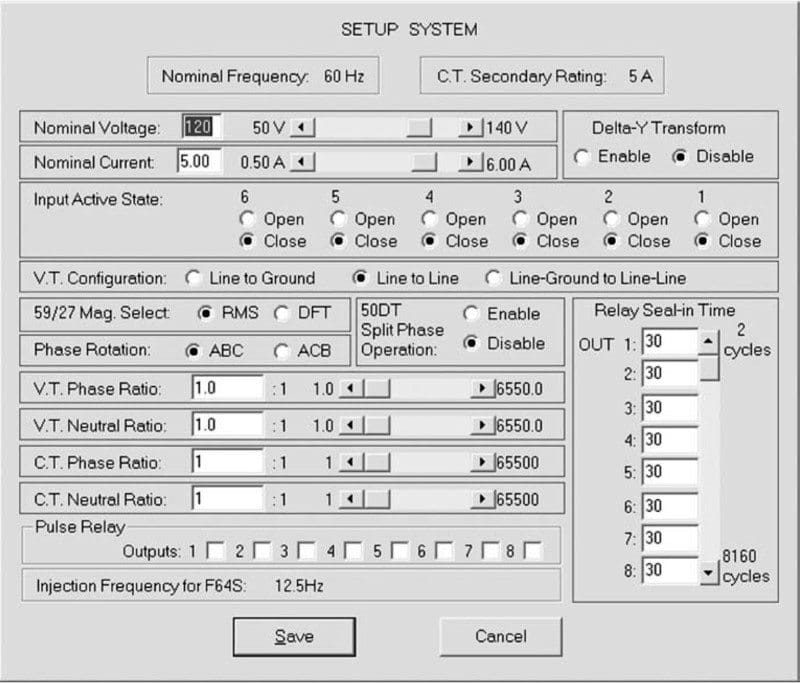
The capability of manually or automatically changing the setting groups to meet the needs of the system is one of the great advantages of using numerical protection. A setting group may be changed immediately when the system topology changes with no compromise on the reliability of the system.
Performance tests
Numerical protection devices are usually not allowed to be field calibrated since they are calibrated by specialised and certified process calibration equipment in the manufacturer’s factory. Protective relay manufacturers perform numerous tests to each device before they are dispatched to customers after they pass the tests.
Most numerical relays, if not all, can be accessed through the front panel (human machine interface (HMI)) or through a serial port using a personal computer (PC).
By accessing the relay with a PC, it is possible to easily perform steady-state and dynamic tests. In some cases, it is the only method to program logic schemes.
1. Acceptance tests
The traditional acceptance tests are used to determine that the relay’s system configuration, protection, control, metering, communication, alarms and reporting features are functional and that their response is in accordance with the manufacturer’s specifications.
They are also used to check that the relay has been correctly installed.
Nowadays, state-of-the-art protective relay test systems are available with graphical test software programs, preconfigured test routines and the capability of personalising test routines that can be later stored for testing similar relays. Most of these software programs do not require computer programming skills to develop automatic relay tests.
A typical scope of acceptance routine tests for numerical protection is as follows:
- Isolate all the relay inputs and outputs signals;
- Verify the correct polarity and supply voltage value;
- Verify that the wiring of all analogue and digital inputs and outputs is correct;
- Electrical insulation test;
- Functional test of all hardware components:
- Binary input/output,
- LCD display, LEDs and any key pad,
- Communication interface,
- Other hardware;
- Setting all the parameters according to a well-documented setting report;
- Tests of all enabled protection functions with secondary current and voltage injection as referred to before; certain elements should be disabled or temporarily modified while testing;
- Verification of operating measured values;
- Tests of the programmable logic scheme(s);
- Test of targets and output contacts;
- Verification of reporting features and alarms;
- Reload/verify the in-service settings into the relay.
2. Functional tests
After the acceptance tests have been performed and it has been verified that the relay can meet the intended specifications, functional tests should be performed. The specific procedure for each relay depends on the type of protection involved and the logic scheme implemented.
A general procedure for carrying out these tests for a numerical protection arrangement is given as follows:
- Verify external AC and DC input signals;
- Verify external input contacts;
- Verify tripping and signalling;
- Verify remote/transferred tripping;
- Verify interaction with the SCADA system, if applicable;
- Verify setting group change according to the logic setting.
Some of these features are logic status report, in-service readings, metering data, event report and oscillographies. The last two features are useful not only for commissioning but also for troubleshooting.
3. Dynamic tests
In a dynamic test, the value of the applied phasors that represent the power system conditions should be properly adjusted when analysing pre-fault load, fault and post-fault states. In this test, there are no typical characteristics of a power system, such as high frequency and DC decrement.
Changes in phasor values (i.e. the magnitude and/or angle) should be controlled in such a manner that they do not present any significant slip during the whole test.
4. Transient simulation tests
The test signal of the transient simulation represents, for the relay, the actual external signals of frequency, magnitude and duration when a disturbance occurs in the power system. These signals may involve offset (DC displacement), the saturation effects of CTs and the response of transient voltage surge suppressors.
5. End-to-end tests
End-to-end testing methodology is appropriate to verify the communication scheme and the protection system in an electrical line at the same time.
Standard end-to-end testing methods use the following resources on each side of the line:
- 3-phase protection relay test equipment with appropriate communication and transient simulation capabilities;
- For the time synchronisation of the two, test equipment could be used with one of the following methods: GPS satellite receiver (currently the most common method), pilot wire and fibre optic, or with the power system;
- Fault simulation such as the Electromagnetic Transients Program (EMTP) or real transient files taken from disturbance recorders.
The EMTP is a computer program for simulating high-speed transient effects in electrical power systems. It includes a wide range of modelling capabilities including oscillations ranging in duration from microseconds to seconds.
These files permit a comprehensive analysis of a particular event to be achieved by using appropriate software and are fed into relay test equipment that can reproduce the original waveform to be injected into a relay under test.
Reference // Protection of Electricity Distribution Networks by Juan M. Gers and Edward J. Holmes (Purchase paperback from Amazon)
Related electrical guides & articles


Edvard Csanyi
Hi, I'm an electrical engineer, programmer and founder of EEP - Electrical Engineering Portal. I worked twelve years at Schneider Electric in the position of technical support for low- and medium-voltage projects and the design of busbar trunking systems.I'm highly specialized in the design of LV/MV switchgear and low-voltage, high-power busbar trunking (<6300A) in substations, commercial buildings and industry facilities. I'm also a professional in AutoCAD programming.
Profile: Edvard Csanyi

Good tests
What’s your email id.
How much short circuit is expected after 13 meters from Transformer of 1600 kVA.
6% IMPEDANCE..2500 A busbar is used upto 12 meter(till LV panel). 1 meter 1600 A is used from LV panel to SMDB,