
Estimated Study Time: 12 minutes
Commissioning substation busbars
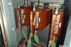
The commissioning procedure of substation busbars for differential protection and other busbar protection schemes involves a large number of input and output circuits that require a verification check in both the primary and secondary circuits.
 New TriRaptor testing device by EuroSMC
This large amount of data adds up to electrical parameter measurements which are related to polarity, the transformation ratio, and the identification of the CTs connected to these protections.
It is a necessary and complex task, which requires technical expertise, along with high current injection equipment that provides an accurate and stable output. This test is one of the most time-consuming tasks in the substation testing and commissioning procedure (normally days) and it is essential that test is executed and reported correctly.
This document will explain how to save a huge amount of time and completely eliminate the possibility of errors, giving a true and accurate report of the state of busbars.
Three phase testing and commissioning
The three phase testing and commissioning of the secondary protection circuits in Substation busbars is a must to achieve maximum security and insure that all is working correctly before energizing the substation. In many countries this is even a mandatory regulation.
These tests are intended to verify the following:
- Provide the correct correlation between the secondary windings of the CT connection, and the phase identification CT # 1 phase A, which corresponds to phase A in the relay), thus ensuring the correct polarity connection of the secondary protection circuit and the correct angle between phases.
- It verifies that the CT ratio and the ratio introduced in the relay are correct.
Obviously, there are more tests that should be made, such as, the transition logic sensitivity of the busbar, in each of the CT groups. This has been, up till now, achieved with secondary injection in which the first verification was made using secondary injection equipment and the final verification with primary injection equipment.
Now this can be done with a new three phase testing system as mentioned in this technical article.
Test methods now used
Below are described 2 most common methods to perform this verification:
Traditional method #1
By injecting single-phase high current into the entire Busbar, using single phase primary injection test equipment, that is powerful enough to inject, as close as possible, the nominal current required. The equipment should also be able to control, with a sufficient accuracy and resolution, the phase angle values and the polarity in the secondary circuit.
As well the various external measurement instruments, such as ammeters and phase angle meters should be used or installed in the primary and/or secondary circuit.
The Busbar has a high, inductive impedance which must be multiplied by two, since you have to inject both ways (back and forth) and the return injection is usually made by using the Busbar of another phase or a neutral if it exists. This requires heavy and large equipment that has the sufficient power to generate enough voltage to reach the necessary current through the busbar.
The main disadvantages of this method are:
The instability of the injection output of the equipment now used, which are those that vary with the mains supply and with the temperature changes of the busbar, which relates the current measurement injected in primary circuit in which the relay is reading at any moment (In secondary circuit).
This means that more tests are need to be perform, to completely test the primary-secondary circuits and is precisely, what takes up most of the time. As well as having a single phase injection equipment the tests needs to be having to repeated for each phase.
Traditional method #2
Short-circuit of an independent three-phase generator connected directly to the busbars.
This method was started when the new digital protection relays were able to store a fault and then offer these results for later analysis. With this method, the current values and their corresponding phase angles can be stored and read.
This is a perfectly valid verification system for the comparison between phases, but it does not offer reliability as the injected values are unknown, unless primary measuring instruments are used, thus presenting the same drawback as previously described.
In short, this is a procedure that is simply used in the absence of a better alternative to the use of a primary current injector set.
Proposed test method
Three-phase primary current injection
From the above information, we can deduce what would be the ideal solution:
First of all, a STABLE and PRECISE, injection system is required to avoid having to use external primary or secondary measurement instruments. That is, for example, if we are injecting, 300 A to the busbar with an accuracy of around 1%, this will allow us to select the current and go to the substation room, to verify the measurement and the corresponding protection relays readings.
Three-phase primary current injection is performed by SMC’s Triraptor device (see technical details).

In order to increase the efficiency of this verification, it is necessary that the current injection is in THREE-PHASE mode, for two fundamental reasons:
Reason #1 – One is by short-circuiting one end of the three busbars and connecting it to ground or having a return conductor.
Also the current injector equipment has a control that sets the three- phase situation (120° between phases) and that the same current value is selected in each. This is an advantage in using all its power in feeding the busbar, since the return current through the short circuit is very small, practically zero.
With very long busbars, this allows to a sufficient test current, since the return current is saved.
Reason #2 – The other reason why an accurate and stable three-phase injection is fundamental, is that it allows to take the necessary time to verify the relay properly with all the measurements, both absolute measurements (phase angle) and relative measurements (the comparisons between the different phases) at same time.
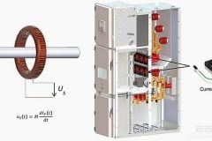
The phase angles reading identifies both the polarity and the correct connection to the relay.
Another great advantage of this injecting system, is that we can also combine this with the digital relays installed, so that the display reading, recording and and consequently making a report.
This is fundamental in saving time as this report is practically automatic, by using the configuration program of the relay itself. In addition, the injection equipment also produces its own report of magnitudes injected, phase angles, the duration, etc.
In short, in a single test operation, we can get a complete report of the busbars, both the secondary connection state and of the protection relays in the system. All this is achieved in a quick and easy way compared to the systems that are presently used for these tests.

Related electrical guides & articles


Edvard Csanyi
Hi, I'm an electrical engineer, programmer and founder of EEP - Electrical Engineering Portal. I worked twelve years at Schneider Electric in the position of technical support for low- and medium-voltage projects and the design of busbar trunking systems.I'm highly specialized in the design of LV/MV switchgear and low-voltage, high-power busbar trunking (<6300A) in substations, commercial buildings and industry facilities. I'm also a professional in AutoCAD programming.
Profile: Edvard Csanyi

Really an usefull information for protection Engineers who test the complicated busbar differential protection