Communication system
A communication system consists of a transmitter, a receiver and communication channels. Type of medias and network topologies in communications provide different opportunities to advance the speed, security, dependability, and sensitivity of protection relays.
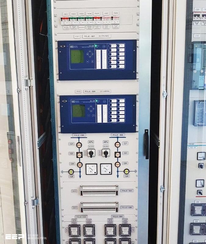
There are a several types of communication media such as micro wave, radio system, fiber optic, etc. The advantages and disadvantages in communication medias which are currently in operation (both analog and digital) and different network topologies are summarized below, respectively.
- Comparison of Communication Medias
- Comparison of Different Communication Network Topologies
- Description of Different Communication Protocols
- Comparison of Relay Characteristics between Different Vendors
1. Comparison of Communication Medias
Let’s start with brief description of seven most known and most used communication medias used in power system communications (in terms of protection and automation):
1.1 Transmission Power Line Carrier
| Advantage(s) | Disadvantage(s) |
| Economical, suitable for station to station communication. Equipment installed in utility owned area. | Limited distance of coverage, low bandwidth, inherently few channels available, exposed to public access. |
1.2 Microwave
| Advantage(s) | Disadvantage(s) |
| Cost effective, reliable, suitable for establishing back bone communication infrastructure, high channel capacity, high data rates. | Line of sight clearance required, high maintenance cost, specialized test equipment and need for skilled technicians, signal fading and multipath propagation. |
1.3 Radio System
| Advantage(s) | Disadvantage(s) |
| Mobile applications, suitable for communication with areas that are otherwise inaccessible. | Noise, adjacent channel interference, changes in channel speed, overall speed, channel switching during data transfer, power limitations, and lack of security. |
1.4 Satellite System
| Advantage(s) | Disadvantage(s) |
| Wide area coverage, suitable to communicate with inaccessible areas, cost independent of distance, low error rates. | Total dependency to remote locations, less control over transmission, continual leasing cost, subject to eavesdropping (tapping). End to end delays in order of 250 ms rule out most protective relay applications. |
1.5 Spread Spectrum Radio
| Advantage(s) | Disadvantage(s) |
| Affordable solution using unlicensed services. | Yet to be examined to satisfy relaying requirement. |
1.6 Leased Phone
| Advantage(s) | Disadvantage(s) |
| Effective if solid link is required to site served by telephone service. | Expensive in longer term, not good solution for multi channel application. |
1.7 Fiber Optic
| Advantage(s) | Disadvantage(s) |
| Cost effective, high bandwidth, high data rates, immune to electromagnetic interference. Already implemented in telecommunication, SCADA, video, data, voice transfer etc. | Expensive test equipment, failures may be difficult to pin-point, can be subject to breakage. |
2. Comparison of Different Communication Network Topologies
2.1 Point-to-Point network
Point-to-Point network is the simplest configuration with channel available only between two nodes.
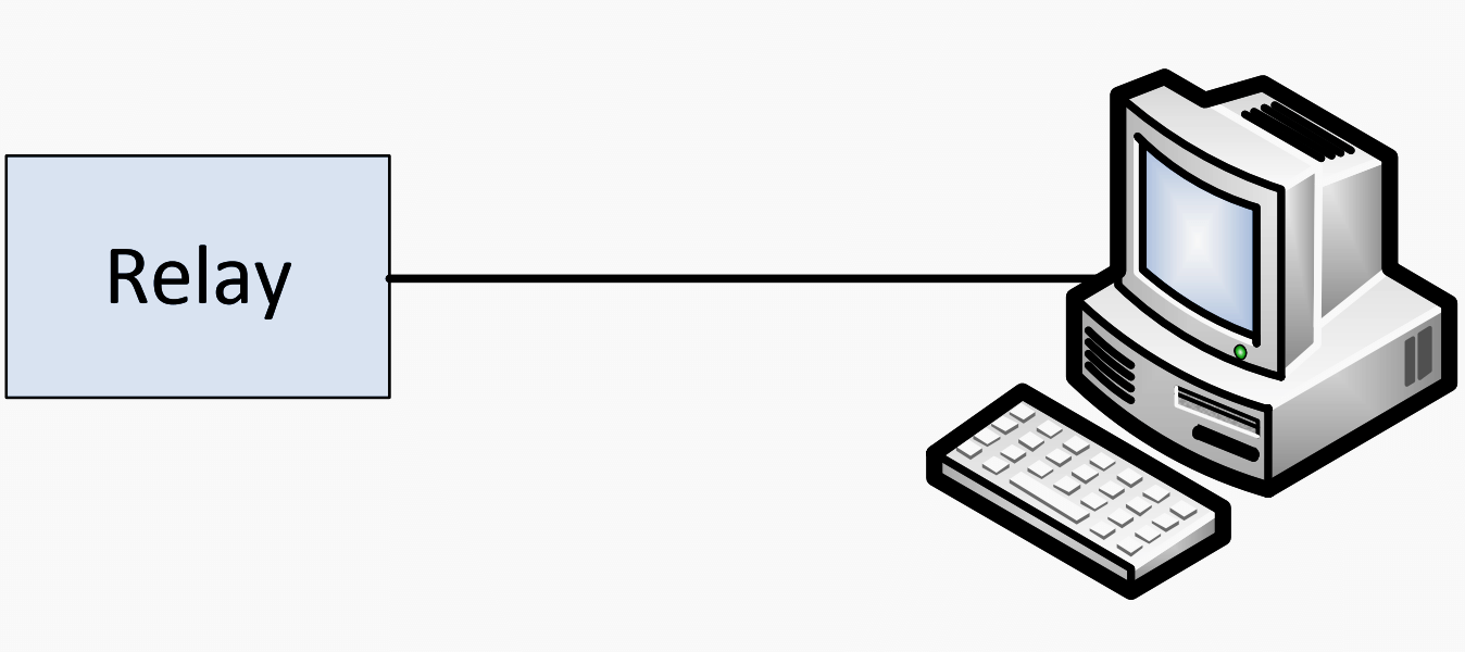

| Advantage(s) | Disadvantage(s) |
| Suitable for systems that require high exchange rate of communication between two nodes. | Communication can only be transferred between two nodes, disconnection of the communication channel will lead to a total loss of information exchange. |
2.2 Star network
Star network consists of multiple point-to-point systems with one common data collector.
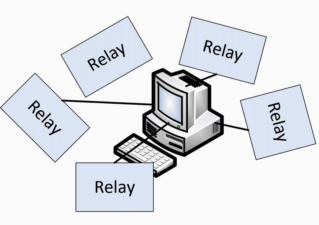

| Advantage(s) | Disadvantage(s) |
| Easy to add and remove nodes, simple in managing and monitoring, node breakdown does not affect rest of the system. | The reliability of entire network depends only on single hub failure. |
2.3 Bus network
Bus network has single communication path which runs throughout the system to connect nodes.
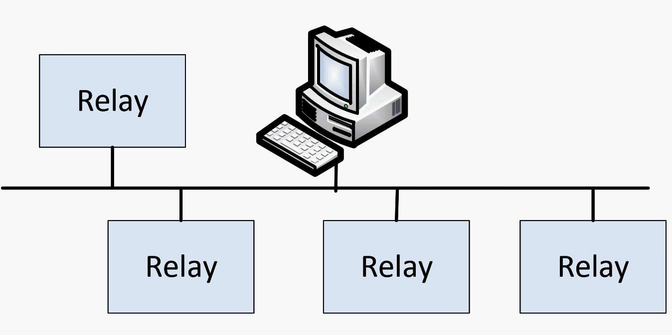

| Advantage(s) | Disadvantage(s) |
| Bus network is not dependent on a single machine (hub). This provides high flexibility in configuration (easy to remove or add nodes and node to node can be directly connected). | High information load might delay the communication traffic speed. Also, it is sometime inefficient to utilize communication channels since the information cannot be exchanged directly between the desired relay and hub without passing through relays along the communication path. In other words, some relays may receive information packets which are unnecessary for them. Thus, it is also hard to troubleshoot the root cause of problem when needed. |
2.4 Linear Drop and Insert network
Linear Drop and Insert network consists of multiple paths for relays to communicate with each other. Information between two non-adjacent nodes can be transferred directly passes through intervening node(s).


| Advantage(s) | Disadvantage(s) |
| When a certain communication channel drops, its bandwidth can be balanced by other channels. | Lack of channel backup against fiber or equipment failure. |
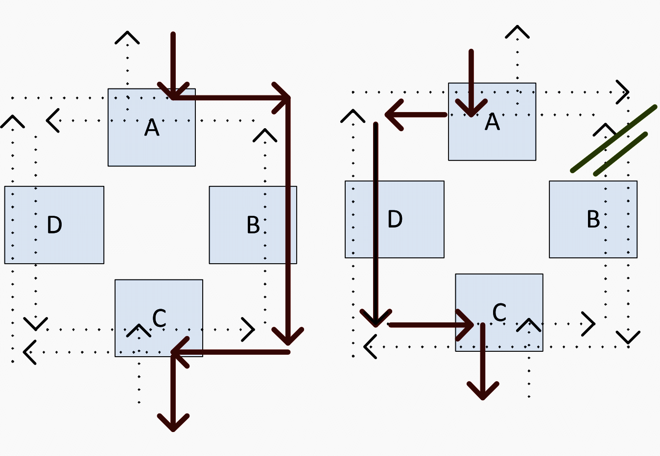
2.5 SONET Path Switched Ring
SONET Path Switched Ring comprises of two separate optical fiber links connecting all the nodes in counter rotating configuration.
In normal case, the information is transferred from A to C through outer ring (via B) which is the primary route (left figure). However if channel failure occurs, the information is transferred through inner ring which is secondary route (right figure).

| Advantage(s) | Disadvantage(s) |
| This type of network is redundant which means that channel failures will not affect the communication process. | An unequal time delay between transmitter and receiver might cause the false operation of protective relays when there is a switch to from primary to secondary route in the case of channel failure. |
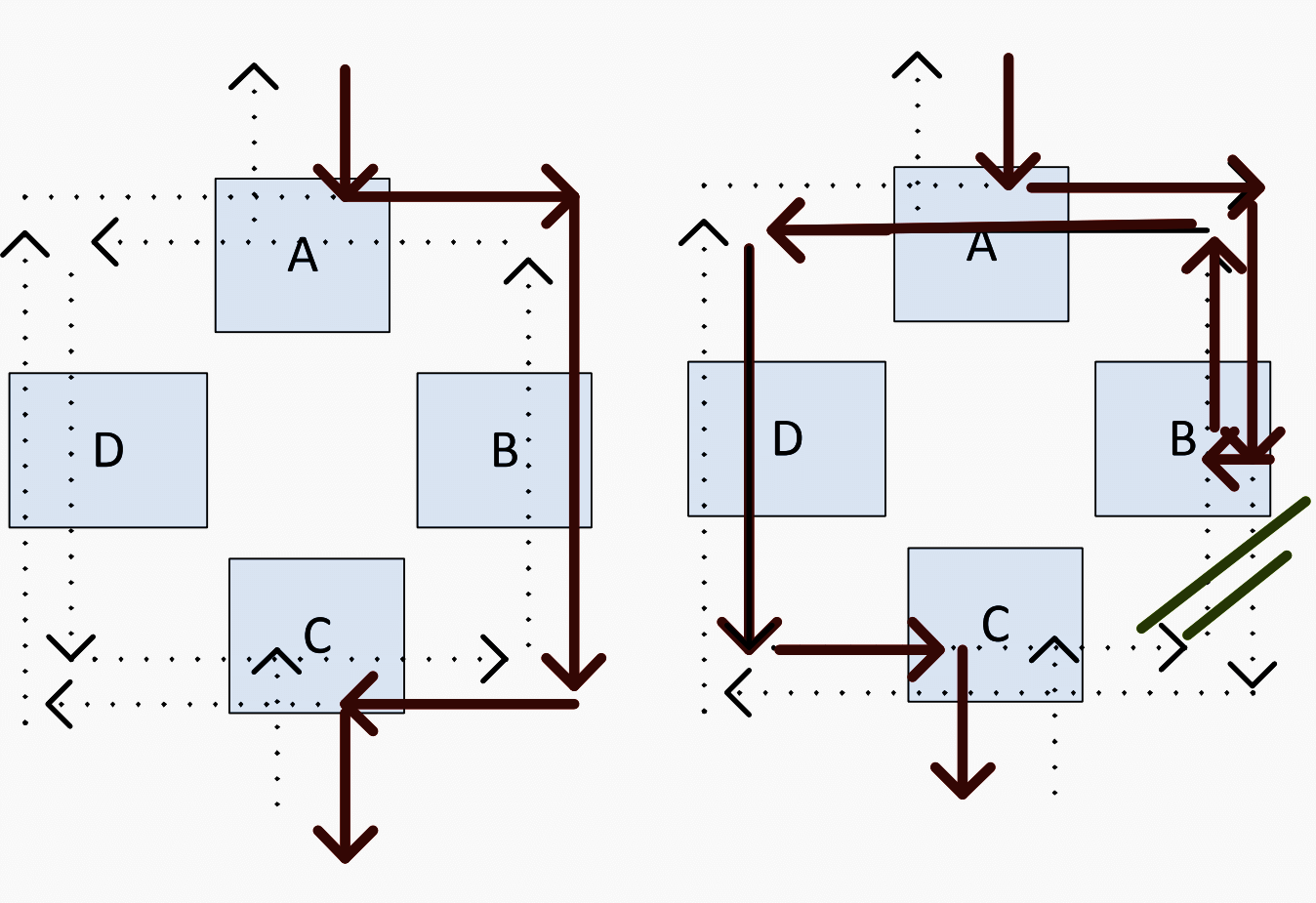
2.6 SONET Line Switched Ring
SONET Line Switched Ring has the same structure as SONET Path type however one path is active and other is a reserved one.
Under normal condition, the active path transfers information via outer ring (left figure). However in case of channel failure, the inner ring is activated to reverse and transmit information through another direction (right figure).

| Advantage(s) | Disadvantage(s) |
| More efficient use of fiber communications for some applications. | This communication type is not suitable for teleprotection applications since it requires complex handshaking (Synchronizing) that causes a delay of 60 ms. |
3. Description of Different Communication Protocols
Communications protocols are sets of rules by which communication over a network is achieved. Communications protocols are responsible for enabling and controlling network communication.
Communication protocols can be categorized into two groups which are (1) Physical-based protocols and (2) Layered-based protocols. Both types of protocol are briefly discussed in this technical article.
3.1 Physical-based protocol
Physical Based-protocols have been developed to ensure compatibility between units provided by different manufacturers, and to allow for a reasonable success in transferring data over specified distances and/or data rates.
In addition, these physical-based protocols are also included in the “Physical layer” of the Open Systems Interconnection (OSI) model that will be explained in Layered-based protocols, section below.
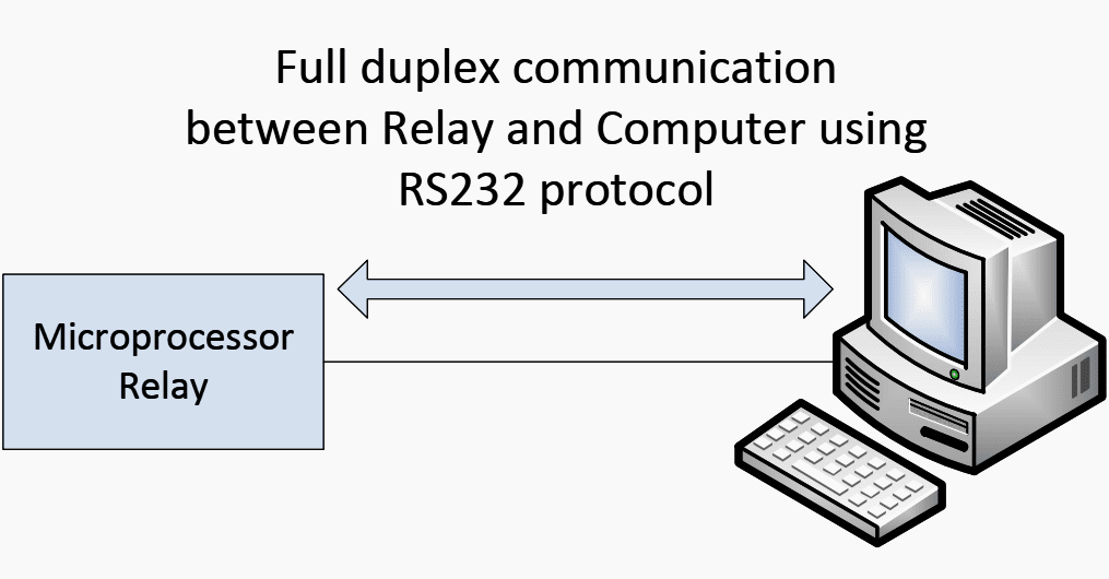
3.1.1 RS232 Protocol
The RS232 Protocol is the most basic communication protocol which specifies the criteria for communication between two devices.
A single twisted pair connection is required between the two devices. Figure 7 shows the RS232 protocol configuration.

3.1.2 RS485 Protocol
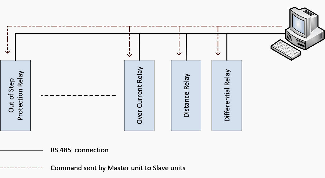
This protocol is similar to the RS232 protocol which allows multiple relays (up to 32) to communicate at half-duplex. This half duplex scheme authorizes one relay either to transmit or receive command information.
This means that the information is handled by polling / responding.
There are two communication modes in RS485 protocol:
- Unicast mode and
- Broadcast mode
In the unicast mode, the “Master unit” sends polling commands, and only one “Slave unit” (assigned by an unique address) responds to its command accordingly. The “Master unit” will wait until it obtains a response from a “Slave unit”or abandon a response in case a pre-defined period expires.
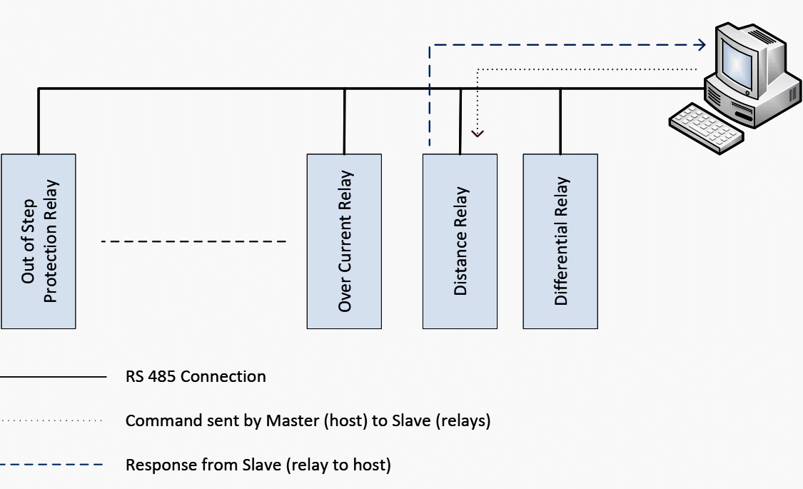

In the broadcast mode, the “Master unit” broadcasts message to all “Slave units”. Figure 8 and 9 show a simple RS485 protocol configuration in the unicast and the broadcast mode, respectively.

3.2 Layered Based-protocols
Other protocols mentioned in Anex table are developed by the Open Systems Interconnection (OSI) model.
This model is a product of the Open Systems Interconnection (OSI) effort at the International Organization for Standardization.
How it works? – The model sub-divides a communication system into several layers. A layer is a collection of similar functions that provide services to the layer above it and receives services from the one below. On each layer, an instance provides services to the instances at the layer above and requests service from the layer below.
When data is transferred from one device to another, each layer would add the specific information to the “headers” and the information will be decrypted at the destination end.
Figure 10 demonstrates data communication using OSI model where “H” represents “headers”.
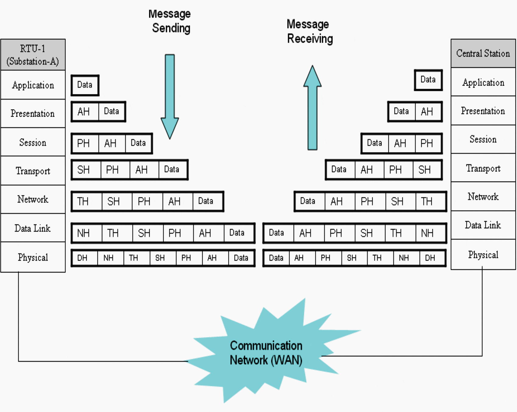

Table 1 below describes function of each layer.
Table 1 – Functions of Open Systems Interconnection (OSI) model
| Layers | Function |
| Application (A) | Offers direct interaction of user with the software application. Adds an application header to the data which defines which type of application has been requested. This forms an application data unit. There are several standards for this layer e.g. HTTP, FTP, etc. |
| Presentation (P) | Handles format conversion to common representation data and compresses and decompresses the data received and sent over the network. It adds a presentation header to the application data unit having information about the format of data and the encryption used. |
| Session (S) | Establishes a dialogue and logical connection with the end user and provides functions like fault handling and crash recovery. It adds a session header to the presentation data unit and forms a session data unit. |
| Transport (T) | Manages the packet to the destination and divides a larger amount of data into smaller packages. There are two transport protocols, Transmission Control Protocol (TCP) and User Datagram Protocol (UDP), in this layer. Reliability and speed are the primary difference between these two protocols. TCP establishes connections between two hosts on the network through packages which are determined by the IP address and port number. TCP keeps track of the packages delivery order and check of those that must be resent. Maintaining this information for each connection makes TCP a stateful protocol. On the other hand, UDP provides a low overhead transmission service, but with less error checking. |
| Network (N) | Controls the routing and addressing of the packages between the networks and conveys the packet through the shortest and fastest route in the network. Adds a network header to the Transport Data Unit which includes the Network Address. |
| Data Link (D) | Specifies Physical Address (MAC Address) and provides functions like error detection, resending etc. This layer adds a Data Link Header to the Network Data Unit which includes the Physical Address. This makes a data link data unit. |
| Physical | Determines electrical, mechanical, functional and procedural properties of the physical medium. |
Some of protocols, mentioned in Anex table, that are derived from OSI model are described below:
3.2.1 DNP 3.0
The Distributed Network Protocol (DNP) 3.0 is a protocol developed to achieve interoperability standard between substation computers.
This protocol adopts layers 1, 2 and 7 from the OSI model for basic implementation. A fourth layer (a pseudo-transport layer) can be added to allow for the message segmentation.
This protocol does not wait for data as TCP/IP. If a packet is delayed, after a while, it will be dropped. This is because the protocol consists of embedded time synchronization (timetag) associated with messages.
This timetag’s accuracy is on the order of milliseconds. It is feasible to exchange messages asynchronously which is shown in a function of the polling/
response rate.
The typical processing throughput rate is 20 milliseconds.
3.2.2 ModBus
ModBus is also a three-layer protocol that communicates using a “master-slave” technique in which only one device (the master) can initiate transactions (called queries).
The other devices (slaves) respond by supplying the requested data to the master, or by taking the action requested in the query.
This protocol does not consist of embedded time synchronization as in case of DNP 3.0 that each message is stored in an internal buffer.
In general, IRIG provides accuracy in the 100 microsecond range but it requires dedicated coaxial cable to transport the timing signals which can be limitation for the number of connected devices (depending on cable length and device load).
On the other hands, GPS provides higher accuracy (in the range of 1 microsecond) compare to IRIG but cost and complications of antennas installation to every device are the restriction for the GPS deployment.
Nevertheless, the choice of time synchronization protocol is usually dictated by the number and type of power system devices as well as the physical arrangement of the equipment. The typical processing throughput rate of ModBus protocol is 8 milliseconds.
The protocol can be categorized into three frame formats which are American Standard Code for Information Interchange (ASCII), Remote Terminal Unit (RTU), and Transfer Control Protocol and Internet Protocol (TCP/IP) format.
The ModBus ASCII and ModBus RTU are both used in serial communication. The difference between these ASCII and RTU frames is the format of communication message. In the ASCII format, two ASCII characters are used in each 8 bit byte message whereas two 4 bit hexadecimal characters (or 8-bit binary) are used in case of the RTU format.
The advantage of ASCII format is that it allows time intervals of up to one second to occur between characters without causing an error.
Figure 11 shows the Protocol Data Unit (PDU) for ASCII and RTU frame formats.
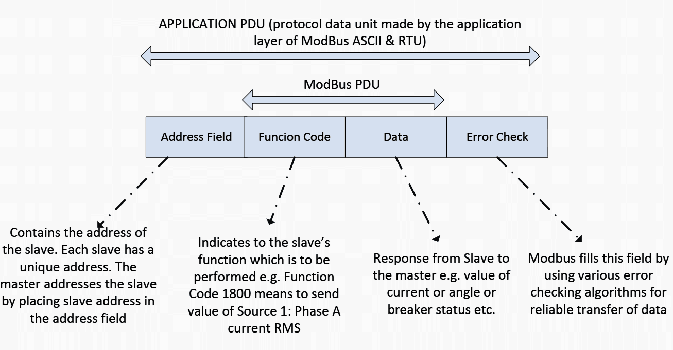

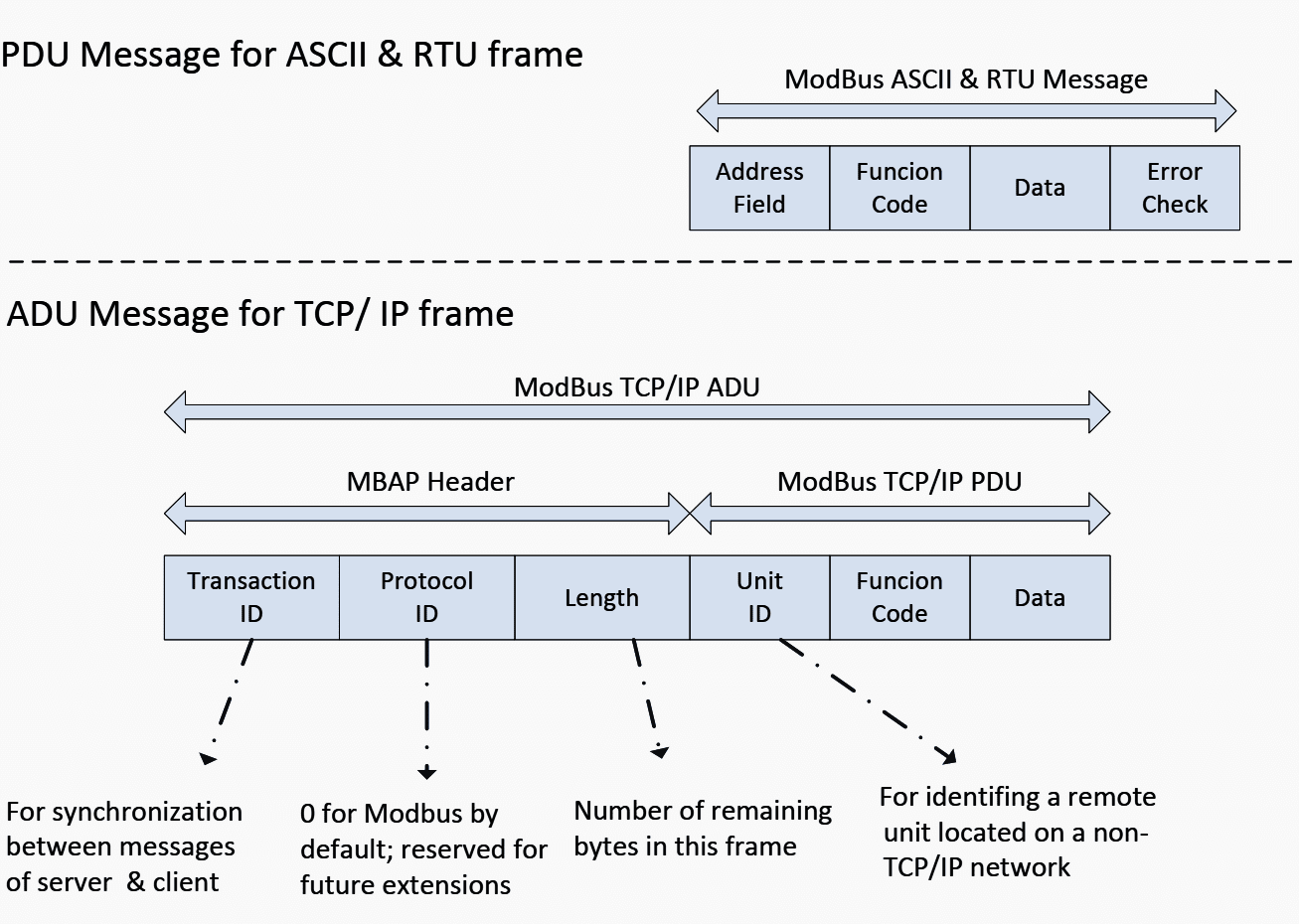
Meanwhile, the ModBus TCP/IP is modified from the PDU frame with the Ethernet-TCP/IP as an additional data transmission technology for the ModBus Protocol.
First, an “Error Check” algorithm at the end of frame is removed and the Address Field (address of slave) is replaced by a new header called the ModBus APplication (MBAP) Header. This header consists of (i) Transaction Identifier, (ii) Protocol Identifier, (iii) Length Field, and (iv) Unit Identifier.
Figure 12 shows the Application Data Unit (ADU) for TCP/IP frame format (compare with PDU message).
The difference between ModBus and DNP 3.0 is the communication purpose. ModBus is suitable for communication within substations that are used for communicating with devices meant for protection control and metering.

Meanwhile DNP 3.0 is suitable for communicate outside the substations (communication of data from substation to master control centers). This is because the ModBus protocol has limited function codes while the DNP 3.0 supports the specific data objects that provide more flexibility, reliability and security.
For example, the DNP 3.0 has ‘Control Function Code’ to perform specific function.
In addition, the ModBus protocol is a prototype for proprietary protocols such as K-BUS and SPA protocols which are of Areva-Alstom and ABB, respectively.
3.2.3 IEC 61850
IEC 61850 is an electrical substation standard promoted by the International Electrotechnical Commission (IEC).
The protocol includes time tags and also messages that can be exchanged asynchronously.
The typical processing throughput rate is 12 milliseconds.
IEC 61850 provides many advantage over other protocols such as programming can be done independent of wiring, higher performance with more data exchange, or data is transmitted multiple times to avoid missing information.
3.2.4 LON
The Local Operating Network (LON) protocol equates all seven layers of the OSI Model. It is capable of establishing network communications not only for power system applications, but also for factory automation, process control, building networks, vehicle networks etc.
This may be considered as a drawback in relay communication perspective since the LON protocol occupies seven layers in order to transfer information, thus it provides lower data exchange rates compare to the EPA model such as DNP 3.0.
ANEX
Comparison of Relay Characteristics between Different Vendors
| Protection relay (Communication Method] | Vendors (their communication methods) | |||
| GE | ABB | SEL | ALSTOM | |
| Generator protection | RS232; RS485; IEC 61850; ModBus TCP/IP; DNP 3.0; IEC 60870-5-104 | RS232; RS485; IEC 61850-8-1; IEC 60870-5-103; LON; SPA; DNP 3.0; ModBus RTU/ASCII | SEL; ModBus TCP/IP; DNP; FTP; IEC 61850; MIRROR BITS; EVMSG; C37.118 (synchrophasors) | RS232; RS485; Courier/K-BUS ModBus; IEC 60870-5-103; DNP 3.0; IEC 61850 |
| Differential protection | ||||
| Distance protection | RS232; RS485; DNP 3.0; ModBus RTU/ASCII | |||
| Over/Under Voltage protection | RS232; RS485; IEC 61850; ModBus TCP/IP; IEC 60870-5-103 | RS232; RS485; IEC 61850-8-1; IEC 60870-5-103; LON; SPA; DNP 3.0; ModBus RTU/ASCII | ||
| Overcurrent protection | EIA 485; ModBus RTU; EIA 232 | |||
Reference // Power System Protective Relaying: basic concepts, industrial-grade devices, and communication mechanisms by Rujiroj Leelaruji and Dr. Luigi Vanfretti (KTH Royal Institute of Technology – Electric Power Systems Department)





At “Communication Network Solutions
for Smart Grids” (version 7.1) in Chapter 8 the requirements for the Communication infrastructure were defined. What has changed in the approaches to using packet technologies and transition all applications to them?
I want to follow you and learn from you
Very informative article, can you send me pdf , thank you
Its very informative , Please send me PDF file of this note
Please could you sende the article in PDF.
Thanks
Please send me the pdf version.
Thanks, It was very informative.
Nice
Thanks
The paper above is very useful, I would be grateful if you could share with us.
Many thanks
Please send me this content’s PDF version in my e-mail address
Please send me this content’s PDF version in my e-mail address
This is really super to learning for the networking.You could send networking related topics. I really likes….
Please send me this content’s PDF version in my e-mail address