


Estimated Study Time: 28 minutes
EMF Influence on Operators & Neighbours
This article provides a comprehensive comparative analysis of Extremely Low Frequency (ELF) electromagnetic fields generated by High Voltage (HV) and Low/Medium Voltage (LV/MV) electrical substations. We explore the fundamental physics of these environments, establishing that electric fields are driven by voltage and easily shielded, whereas magnetic fields are driven by current and are highly penetrating.
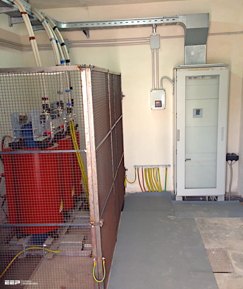 Comparison of Electromagnetic Fields in LV/MV and HV Power Substations
The discussion breaks down HV Air Insulated Substations (AIS), where immense voltages produce formidable electric fields that pose acute micro-shock hazards to occupational personnel.
In contrast, we examine how Gas Insulated Switchgear (GIS) and metallic enclosures completely eradicate external electric fields while concentrating magnetic forces locally.
We then shift focus to urban LV/MV distribution substations, which operate at lower voltages but generate large secondary currents that create severe, unshielded magnetic fields.
A central irony explored is that large HV transmission yards rarely expose neighbors to significant fields, whereas compact LV/MV substations embedded in residential basements directly radiate into adjacent apartments.
Finally, we detail practical engineering mitigation strategies, highlighting how phase compaction and specialized ferromagnetic shielding are utilized to harmonize dense electrical distribution with human health guidelines.
- Introduction to Extremely Low Frequency (ELF) Environments
- The Physics of Substation Electromagnetic Fields:
- HV Substations: Field Topologies and Exposures:
- Low and Medium Voltage (LV/MV) Substations: Urban Integration:
- Influence on Substation Operators (Occupational Exposure):
- Influence on Neighbours (Public Exposure):
- Engineering Mitigation Strategies:
- Measurement and Dosimetry
- Conclusion
- Attachment (PDF) 🔗 Download ‘Design handbook For Electric Machines, Transformers, and Power Systems (11.4 MB)’
1. Introduction to Extremely Low Frequency (ELF) Environments
The global infrastructure for electricity generation, transmission, and distribution operates predominantly at power frequencies of 50 Hz or 60 Hz. These frequencies fall into the Extremely Low Frequency (ELF) spectrum (defined as 3 Hz to 3 kHz). Within this spectrum, electric and magnetic fields are uncoupled, meaning they exist independently of one another and must be analyzed as separate physical phenomena.
The environment in and around electrical substations presents a complex spatial distribution of these fields, varying significantly depending on the voltage level, current magnitude, phase arrangement, and physical geometry of the busbars and switchgear.
Understanding the distinction between High Voltage (HV) transmission substations and Low/Medium Voltage (LV/MV) distribution substations is critical for evaluating exposure profiles. Electric fields (measured in Volts per meter, V/m) are directly proportional to the voltage of the energized conductors.
Because power systems operate under varying load conditions, magnetic fields are highly dynamic, fluctuating with daily and seasonal demand cycles, whereas electric fields remain relatively constant as long as the equipment is energized.
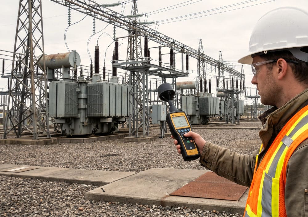
Figure 1 – Measuring Extremely Low Frequency (ELF) in a Switchyard
2. The Physics of Substation Electromagnetic Fields
2.1 Electric Field Generation and Attenuation
Electric fields originate from the potential difference between energized conductors and the ground potential. In an open-air substation environment, the electric field strength at any given point is determined by the complex superposition of fields generated by multiple three-phase conductors.
The field gradient is steepest immediately adjacent to the conductor surface and diminishes rapidly with distance (inversely proportional to the square of the distance for point sources, or linearly for infinite line charges).
Consequently, while electric fields within an HV substation yard can be severe, they are almost entirely attenuated outside the perimeter fence or inside nearby brick or concrete structures.
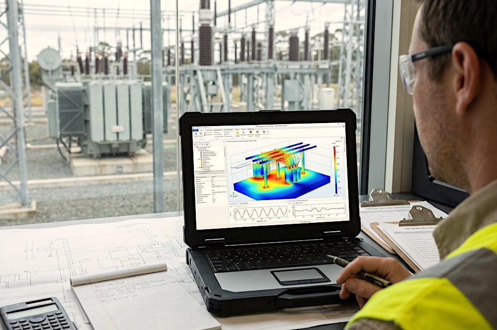
Figure 2 – Mesuring Switchyard Electric Field Through Application
2.2 Magnetic Field Generation and Permeation
Magnetic fields are generated by the motion of electric charges (current). In three-phase AC systems, the resultant magnetic field at any point in space is a rotating vector ellipsoid, continuously changing in magnitude and direction. The magnitude depends not only on the current in each phase but critically on the spatial separation between the phase conductors.
If the three phase conductors could occupy the exact same physical space, their magnetic fields (being 120 degrees out of phase) would perfectly cancel each other out. Because physical separation is required for electrical insulation, perfect cancellation is impossible, resulting in a net magnetic field in the surrounding area.
Therefore, a magnetic field generated inside a substation will pass unhindered through concrete walls and fences, affecting adjacent properties and public spaces.
Recommended Tool (XLSX) – Calculation of electro magnetic field (EMF) around T&D overhead lines
Calculation of electro magnetic field (EMF) around T&D overhead lines
3. High Voltage (HV) Substations: Field Topologies and Exposures
High voltage substations (typically operating between 110 kV and 765 kV) serve as the critical nodes in the transmission grid. These facilities require vast amounts of land to maintain the air clearances necessary to prevent dielectric breakdown (arcing) at such high potentials.
The primary technologies employed are Air Insulated Switchgear (AIS) and Gas Insulated Switchgear (GIS).
3.1 Air Insulated Substations (AIS)
In an AIS, atmospheric air serves as the primary dielectric medium. The phase-to-phase and phase-to-ground clearances are necessarily large. Due to the high operating voltages, the unperturbed electric fields directly beneath the main busbars can easily reach between 5 kV/m and 15 kV/m.
The highest electric field gradients are typically found near sharp edges of hardware, disconnect switch blades, and the lower sections of grading rings.
Directly beneath a heavily loaded 400 kV busbar, magnetic fields might range from 10 µT to 50 µT. Because of the sheer size of the AIS yard, these fields usually decay to background levels (below 0.5 µT) long before reaching the perimeter fence.
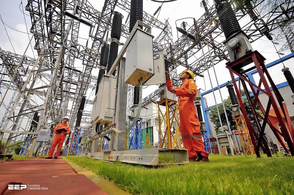
Figure 3 – Operators checking equipment in air-insulated substations (AIS)
3.2 Gas Insulated Substations (GIS)
GIS technology utilizes sulfur hexafluoride (SF6) or modern environmentally friendly alternative gas mixtures as the dielectric medium, allowing for extreme compaction. The energized high-voltage conductors are housed concentrically within grounded metallic enclosures.
The grounded metallic enclosures act as perfect Faraday cages, completely eliminating external electric fields. An operator standing next to an energized 400 kV GIS module will experience an electric field close to 0 V/m.
This results in highly localized, spatially concentrated magnetic fields. Very close to the enclosure surface, the magnetic field can be exceptionally high (sometimes exceeding 100 µT to 300 µT), but it decays extremely rapidly with distance. A few meters away from the GIS hall, the field is negligible.
Further Study – A Schematic Walkthrough of a 132kV GIS Local Control Cabinet (Document Included, PDF)
A Schematic Walkthrough of a 132kV GIS Local Control Cabinet (Document Included, PDF)
4. Low and Medium Voltage (LV/MV) Substations: Urban Integration
Distribution substations step down the voltage from the MV network (e.g., 10 kV, 20 kV, 35 kV) to the LV network (e.g., 400 V / 230 V) for end-user consumption. Unlike HV substations, which are typically sited in isolated areas, LV/MV substations are aggressively integrated into the urban fabric.
They are found in standalone kiosk enclosures on sidewalks, underground vaults, or directly integrated into the ground floors or basements of residential and commercial buildings.
4.1 Field Profiles in LV/MV Environments
Because the operating voltage is relatively low and the equipment is almost entirely housed within grounded metallic cabinets (Ring Main Units, transformer tanks, low voltage feeder pillars), the external electric field generated by LV/MV substations is virtually zero. Neither operators nor neighbours are exposed to significant electric fields from these installations.
The magnetic field profile, however, presents a unique engineering challenge. The fundamental principle of electrical power (P = V × I) dictates that as voltage is stepped down, current must proportionally increase to deliver the same power. A relatively small 1000 kVA distribution transformer will draw less than 30 A on the 20 kV primary side, but will output roughly 1,440 A on the 400 V secondary side at full load.
Because these substations share structural walls with residential apartments or offices, this H-field directly permeates adjacent occupied spaces.
Further Study – Placement and rating planning of feeders & transformers for LV/MV distribution networks
Placement and rating planning of feeders & transformers for LV/MV distribution networks
5. Influence on Substation Operators (Occupational Exposure)
Substation operators, maintenance crews, and electrical engineers are classified under “occupational exposure” in international guidelines. It is assumed that these individuals are healthy adults who are aware of the risks and are trained to take appropriate precautions.
5.1 Occupational Regulatory Frameworks
The most globally recognized exposure guidelines are published by the International Commission on Non-Ionizing Radiation Protection (ICNIRP) and the Institute of Electrical and Electronics Engineers (IEEE C95.6).
The limits are primarily designed to prevent acute, short-term electrophysiological effects, such as the stimulation of the central nervous system, muscle contractions, and retinal phosphenes (flickering visual sensations caused by induced currents in the retina).
- ICNIRP 2010 Occupational Limits (50 Hz): Magnetic Field: 1000 µT. Electric Field: 10 kV/m
- IEEE C95.6 Occupational Limits (60 Hz): Magnetic Field: 2710 µT. Electric Field: 20 kV/m
5.2 Practical Occupational Effects in HV Substations
In high voltage AIS environments, operators are regularly exposed to electric fields approaching or temporarily exceeding the 10 kV/m threshold. The most common physiological effect experienced is the “micro-shock“.
When a grounded operator walks through a high electric field, they distort the field, drawing capacitive displacement currents. If the operator touches a large, ungrounded metallic object (like a parked vehicle or a floating piece of equipment), a transient spark discharge occurs, causing a sharp, stinging sensation. Conversely, if an ungrounded operator (e.g., wearing thick rubber-soled boots) touches a grounded structure, a similar discharge occurs.
To mitigate these effects during live-line maintenance or extended work in highly energized zones, operators wear conductive Faraday suits (woven with stainless steel or silver threads) that completely envelop the body and tie it to the local potential, effectively dropping the internal electric field to zero.
Figure 4 – Basic electric shock situations

5.3 Practical Occupational Effects in LV/MV Substations
In distribution substations and GIS halls, occupational concerns shift entirely from electric fields to magnetic fields. While magnetic fields rarely exceed the 1000 µT occupational limit during normal operation, they can spike dramatically during fault conditions or near unshielded induction heating equipment.
The primary occupational hazard in high magnetic field environments involves Active Implantable Medical Devices (AIMDs), such as pacemakers and implantable cardioverter-defibrillators (ICDs).
Therefore, operators with AIMDs face strict access restrictions, often limited to environments below 100 µT.
Good Reading – Earthed vs. Unearthed Cables in LV and MV Applications
6. Influence on Neighbours (Public Exposure)
The general public encompasses a much wider demographic, including infants, pregnant women, the elderly, and the chronically ill. Consequently, public exposure limits are significantly more stringent, factoring in continuous, lifetime exposure (24 hours a day, 7 days a week) without the subject’s knowledge or explicit consent.
6.1 Public Regulatory Frameworks
Regulatory bodies apply larger safety factors when defining limits for the general public, primarily to protect against the same acute neurological effects mentioned above, but tailored for the most sensitive members of the population.
- ICNIRP 2010 Public Limits (50 Hz): Magnetic Field: 200 µT. Electric Field: 5 kV/m.
- IEEE C95.6 Public Limits (60 Hz): Magnetic Field: 904 µT. Electric Field: 5 kV/m.
6.2 Epidemiological Concerns and the “Precautionary Principle”
While the ICNIRP and IEEE limits prevent acute physical effects, public anxiety regarding substation proximity is almost entirely driven by the fear of long-term epidemiological effects, specifically, the potential link between chronic, low-level magnetic field exposure and childhood leukemia.
This concern originated from the landmark 1979 Wertheimer and Leeper study in Colorado, which suggested a statistical correlation between residential proximity to power lines and childhood cancer rates.
Reasonable, low-cost steps should be taken to minimize public exposure to magnetic fields, often setting local spatial planning limits far below international acute limits (e.g., Switzerland limits new installations to 1 µT at places of sensitive use, and Italy enforces a quality target of 3 µT).
Good Reading – Dangerous contact currents induced by electrical field in 400 kV substations
Dangerous contact currents induced by electrical field in 400 kV substations
6.3 Exposure from HV Substations for Neighbours
Ironically, despite their visual impact and high operating voltages, HV substations rarely pose significant EMF exposure issues for neighbors. The large physical footprint required for electrical insulation serves as an intrinsic safety buffer. The intense electric and magnetic fields generated by the busbars and transformers decay significantly over the tens or hundreds of meters between the equipment and the property line.
By the time the fields reach the boundary fence of a 400 kV substation, the magnetic field is often indistinguishable from the background fields generated by local household appliances.
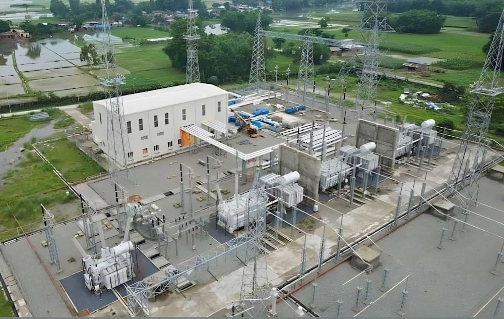
Figure 5 – Hetauda-Dhalkebar-Duhabi 400 kV Substation
6.4 Exposure from LV/MV Substations for Neighbours
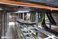
The most acute public exposure challenges arise from built-in LV/MV distribution substations. A substation located in the basement of a residential apartment complex places hundreds of amperes of 400 V distribution cabling mere centimeters beneath the floorboards of the apartment above.
Because common construction materials provide zero magnetic shielding, the residents living immediately adjacent to or above the substation room can be continuously exposed to magnetic fields ranging from 1 µT to 15 µT, well above the 0.4 µT epidemiological threshold.
Utility companies frequently face complaints and legal challenges from neighbors living next to these built-in transformers, necessitating expensive retroactive shielding interventions.
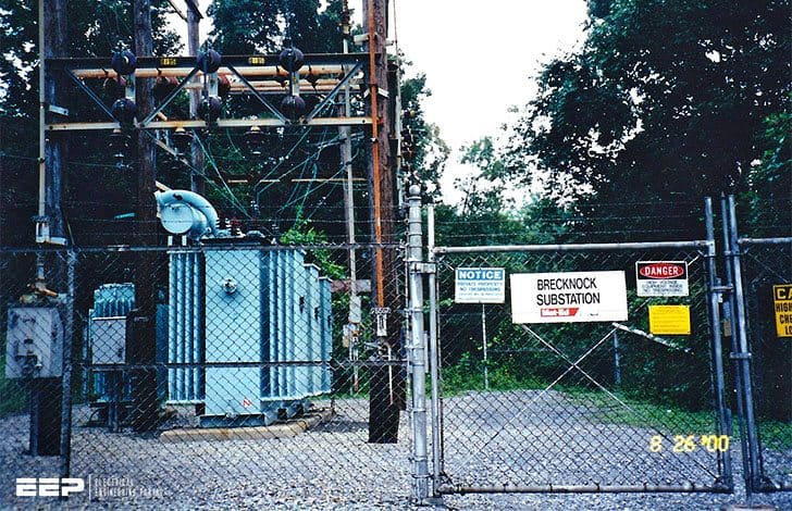
Figure 6 – Distribution Substation
7. Engineering Mitigation Strategies
When electromagnetic field levels exceed regulatory limits or local precautionary thresholds, specific engineering interventions are required. The approach differs entirely depending on whether the target is the electric or the magnetic field.
7.1 Electric Field Mitigation
Electric fields are easily managed. In HV yards, raising the height of the busbars, installing grounded wire meshes (Faraday cages) over walkways, and planting vegetation along the perimeter are highly effective methods.
Simply utilizing metallic enclosures, as seen in GIS and standard MV distribution panels, completely eradicates external electric fields.
7.2 Magnetic Field Mitigation
Mitigating magnetic fields is exceptionally difficult and expensive, particularly for retrofitting LV/MV substations embedded in residential buildings. Mitigation strategies fall into three categories:
Table 1 – Mitigation strategies
| Mitigation Strategy | Description | Application and Effectiveness |
| Phase Compaction and Geometry | Physically moving the three phase conductors closer together to maximize the vector cancellation of their respective magnetic fields. | Highly effective and low cost if implemented during the design phase. Replacing spaced busbars with closely bundled insulated cables reduces fields drastically. |
| Optimal Phase Arrangement | In parallel circuits (e.g., double-circuit overhead lines or parallel busbars), arranging the phases to maximize cancellation (e.g., L1-L2-L3 next to L3-L2-L1). | Highly effective for transmission lines and long busbar runs. Can achieve a 40-60% reduction in peak field levels. |
| Passive Shielding (Eddy Current) | Installing thick plates of highly conductive materials (pure aluminum or copper) on the walls or ceilings adjacent to the source. | The alternating magnetic field induces eddy currents in the plate, which in turn generate an opposing magnetic field. Effective for built-in LV/MV substations, achieving 10 dB to 15 dB of attenuation. |
| Passive Shielding (Flux Shunting) | Installing materials with extremely high magnetic permeability (grain-oriented silicon steel, Mu-metal). | The material acts as a “pipe” for the magnetic flux, channeling it away from the protected area. Highly effective but mechanically complex and expensive to install properly. |
| Active Shielding | Installing large coils around the perimeter of the protected area, driven by a specialized amplifier that injects a current exactly out of phase with the ambient magnetic field. | Rarely used in power systems due to maintenance overhead; primarily reserved for protecting highly sensitive equipment like MRI machines or electron microscopes. |
8. Measurement and Dosimetry
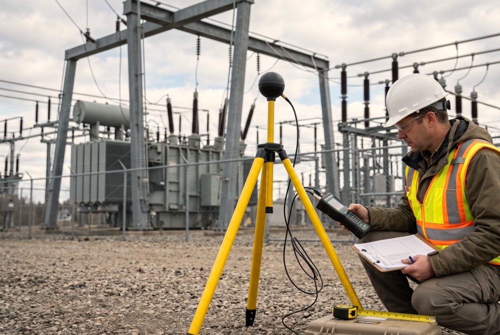
Validating theoretical field levels requires rigorous empirical measurement using calibrated instrumentation. For ELF fields, engineers utilize 3-axis isotropic field meters equipped with specialized probes. Electric field probes measure the displacement current between parallel plates, while magnetic field probes rely on three mutually orthogonal induction coils (Hall effect sensors are generally not sensitive enough for environmental ELF measurement).
When measuring in a substation environment, spatial gradients must be carefully mapped.
Because magnetic fields fluctuate with load, a momentary measurement of 2 µT taken during a low-load night shift might correspond to a 10 µT field during peak afternoon demand. Engineers must scale their measured values against the historical peak load of the facility to determine the true maximum exposure.
Figure 7 – Engineer using 3-axis isotropic field meter in a substation
9. Conclusion
The comparative analysis of electromagnetic fields in High Voltage versus Low and Medium Voltage substations reveals a fascinating engineering dichotomy. High Voltage facilities, characterized by immense electric potentials and expansive geometries, generate formidable electric fields that present tangible acute risks (micro-shocks) to occupational personnel.
However, their isolated locations and large physical footprints naturally protect the general public from significant exposure.
Protecting both operators and neighbors requires deep technical foresight, utilizing advanced compaction, clever phase geometries, and strategic ferromagnetic shielding to harmonize the delivery of dense electrical energy with stringent human health guidelines.
Suggested Course – Comprehensive Masterclass: Learn Line Protection Panel Schematics (UK, US, EU, Middle East, and Asian Standards)
9. Attachment (PDF): Design handbook For Electric Machines, Transformers, and Power Systems
Download: Design handbook For Electric Machines, Transformers, and Power Systems (for premium members only):
Related electrical guides & articles





Edvard Csanyi
Hi, I'm an electrical engineer, programmer and founder of EEP - Electrical Engineering Portal. I worked twelve years at Schneider Electric in the position of technical support for low- and medium-voltage projects and the design of busbar trunking systems.I'm highly specialized in the design of LV/MV switchgear and low-voltage, high-power busbar trunking (<6300A) in substations, commercial buildings and industry facilities. I'm also a professional in AutoCAD programming.
Profile: Edvard Csanyi