Search

Premium Membership ♕

Save 50% on all EEP Academy courses with Enterprise Membership Plan and study specialized LV/MV/HV technical articles, guides and courses.

Home / Technical Articles / How to determine compensation of reactive power of an electrical installation

Improving power factor

Improving the power factor of an electrical installation (compensation of reactive power) has many economic and technical advantages, but it’s not always easy to do so. There are numerous approaches to do such job, so let’s try to with this one.

How to determine compensation of reactive power of an electrical installation
How to determine compensation of reactive power of an electrical installation (photo credit: egc-cb.cz)

Compensation of an installation is determined in four steps:

  1. Calculating reactive power
  2. Choosing the compensation mode:
    1. Global compensation for the entire installation
    2. Compensation by sector
    3. Individual load compensation
  3. Choosing the compensation type:
    1. Fixed
      (by switching on/off a capacitor bank supplying a fixed amount of kvar)
    2. Automatic
      (by switching on/off “steps” by breaking up installed bank capacity and enabling adaptation in the installation’s kvar needs)
  4. Allowing for harmonics
    This involves choosing the right equipment to avoid the harmful consequences that harmonics might have on the capacitors installed.

These steps are developed as follows:


1. First step – Calculating the reactive power


Calculation Principle:

The aim is to determine the reactive power Qc (kvar) to be installed to increase the cos 𝜑 of the installation to reach a given target.

This involves going from:

  • cos 𝜑1 → cos 𝜑2 where cos 𝜑2 > cos 𝜑1
  • 𝜑1 → 𝜑2 where 𝜑2 < 𝜑1
  • tan 𝜑1 → tan 𝜑2 where tan 𝜑2 < tan 𝜑1
  • Q → QL – QC where QL is load reactive power
  • S1 → S2 where S2 < S1.

This is illustrated in Figure 1 below.
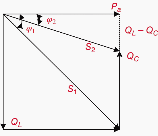
Figure 1 – Determination of reactive power Qc

Calculation by Using Installation Data:

The power to be installed is calculated from cos 𝜑1 or from tan 𝜑1 noted for the installation. The aim is to move to a value of cos 𝜑2 or tan 𝜑2 thus improving the operation, as shown in Figure 1.

QC can be calculated from the equation: QC = Pa(tan 𝜑1 − tan 𝜑2),

which results from the figure, where

  • QC = rating of the capacitor bank in kvar,
  • Pa = active power of the load in kW,
  • tan 𝜑1 = tangent of the phase angle (V, I) of the installation, and
  • tan 𝜑2 = tangent of the phase angle (V, I) after installation of the capacitor bank.

QC can also be calculated by using Table 1. The equation of QC can be rewritten as:

QC = k Pa

where k is a factor determined very easily from Table 1 if one knows tan 𝜑1 or cos 𝜑1 of the existing installation and tan 𝜑2 or cos 𝜑2, which is to be obtained.

For instance, if the installation PF (cos 𝜑1) is 0.71 and required to be 0.94 (cos 𝜑2), then the factor k is equal to 0.63, which in turn means that the reactive power capacity required for compensation is 63% of the active power demand.

Go back to contents ↑


2. Second step – Choosing the compensation mode

Where to install capacitors? Installation of capacitors on an electrical network is referred to as the “compensation mode”.

It is determined by the objective (eliminating penalties, relieving stress on cables and transformers and improving network voltage), the electrical power distribution mode, the load system, the predictable effect of capacitors on network characteristics, and the cost of the installation.

Table 1 –  Capacitor Bank Sizing
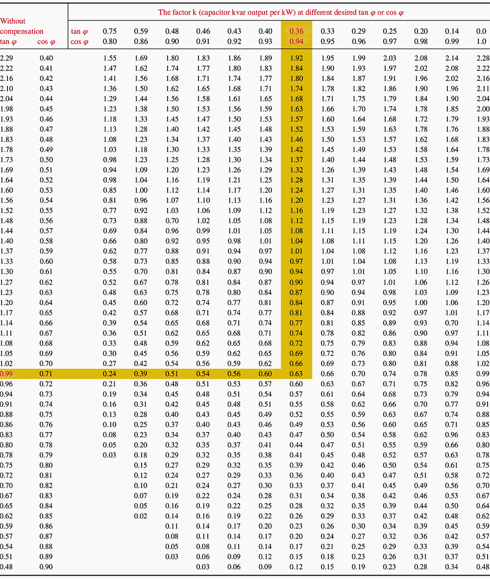
Capacitor Bank Sizing
Table 1 – Capacitor Bank Sizing

Reactive power compensation can be:

  • Global
  • By sector
  • By individual load.

It is more economical to install capacitor banks in MV and HV for powers greater than approximately 800 kvar.

Analysis of networks in various countries proves, however, that there is no universal rule. The compensation mode depends on the energy policy of the countries and electricity boards.

In the United States, compensation is mainly at MV for tariff policy reasons, whereas in Germany, compensation is at LV. In France, the utility installs fixed banks on 63- and 90-kV networks (bank not broken up) and switched step banks (bank broken up) in MV source substations on 11-, 22- and 33-kV networks.

The latter’s power can reach 4.8 Mvar at 22 kV.
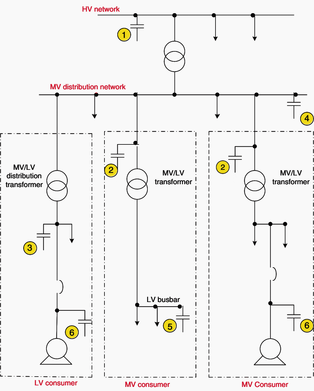
Compensation modes
Figure 3 – Compensation modes

Go back to contents ↑


Global Compensation

The capacitor bank is connected at the supply end of the installation to be compensated and provides compensation for the entire installation. It is ideal for stable and continuous loads.

Membership Upgrade Required

This content is not available in your premium membership plan. Please upgrade your plan in order to access this content. You can choose an annually based Basic, Pro, or Enterprise membership plan. Subscribe and enjoy studying specialized technical articles, online video courses, electrical engineering guides, and papers.

With EEP’s premium membership, you get additional essence that enhances your knowledge and experience in low- medium- and high-voltage engineering fields.

Good to know 💡Save 50% on all courses with Enterprise membership plan.

Upgrade

Already a member? Log in here

Copyright Notice

This technical article is protected by U.S. and international copyright laws. Reproduction and distribution of PDF version of this technical article to websites such as Linkedin, Scribd, Facebook and others without written permission of the sponsor is illegal and strictly prohibited.

© EEP-Electrical Engineering Portal.

Premium Membership

Get access to premium HV/MV/LV technical articles, electrical engineering guides, research studies and much more! It helps you to shape up your technical skills in your everyday life as an electrical engineer.
More Information
Edvard Csanyi - Author at EEP-Electrical Engineering Portal

Edvard Csanyi

Hi, I'm an electrical engineer, programmer and founder of EEP - Electrical Engineering Portal. I worked twelve years at Schneider Electric in the position of technical support for low- and medium-voltage projects and the design of busbar trunking systems.

I'm highly specialized in the design of LV/MV switchgear and low-voltage, high-power busbar trunking (<6300A) in substations, commercial buildings and industry facilities. I'm also a professional in AutoCAD programming.

Profile: Edvard Csanyi

Leave a Comment

Tell us what you're thinking. We care about your opinion! Please keep in mind that comments are moderated and rel="nofollow" is in use. So, please do not use a spammy keyword or a domain as your name, or it will be deleted. Let's have a professional and meaningful conversation instead. Thanks for dropping by!

71  −  sixty one  =  

Learn How to Design Power Systems

Learn to design LV/MV/HV power systems through professional video courses. Lifetime access. Enjoy learning!

EEP Hand-Crafted Video Courses

Check more than a hundred hand-crafted video courses and learn from experienced engineers. Lifetime access included.
Experience matters. Premium membership gives you an opportunity to study specialized technical articles, online video courses, electrical engineering guides, and papers written by experienced electrical engineers.