
Estimated Study Time: 16 minutes

Continued from article Complete overview of lightning arresters (part 2)
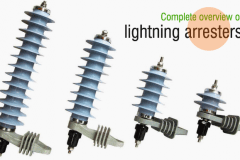
Types of Lightning Arresters for outdoor application
There are several types of lightning arresters in general use. They differ only in constructional details but operate on the same principle, providing low resistance path for the surges to the round.
- Rod arrester
- Horn gap arrester
- Multi gap arrester
- Expulsion type lightning arrester
- Valve type lightning arrester
(1) Rod gap arrester
It is a very simple type of diverter and consists of two 1.5 cm rods, which are bent at right angles with a gap in between as shown in Fig. One rod is connected to the line circuit and the other rod is connected to earth. The distance between gap and insulator (i.e. distance P) must not be less than one third of the gap length so that the arc may not reach the insulator and damage it.
Generally, the gap length is so adjusted that breakdown should occur at 80% of spark-voltage in order to avoid cascading of very steep wave fronts across the insulators.
The string of insulators for an overhead line on the bushing of transformer has frequently a rod gap across it. Fig 8 shows the rod gap across the bushing of a transformer. Under normal operating conditions, the gap remains non-conducting. On the occurrence of a high voltage surge on the line, the gap sparks over and the surge current is conducted to earth. In this way excess charge on the line due to the surge is harmlessly conducted to earth

Limitations
- After the surge is over, the arc in the gap is maintained by the normal supply voltage, leading to short-circuit on the system.
- The rods may melt or get damaged due to excessive heat produced by the arc.
- The climatic conditions (e.g. rain, humidity, temperature etc.) affect the performance of rod gap arrester.
- The polarity of the f the surge also affects the performance of this arrester.
Due to the above limitations, the rod gap arrester is only used as a back-up protection in case of main arresters.
(2) Horn gap arrester
Fig shows the horn gap arrester. It consists of a horn shaped metal rods A and B separated by a small air gap. The horns are so constructed that distance between them gradually increases towards the top as shown. The horns are mounted on porcelain insulators. One end of horn is connected to the line through a resistance and choke coil L while the other end is effectively grounded.
The resistance R helps in limiting the follow current to a small value. The choke coil is so designed that it offers small reactance at normal power frequency but a very high reactance at transient frequency. Thus the choke does not allow the transients to enter the apparatus to be protected.
The gap between the horns is so adjusted that normal supply voltage is not enough to cause an arc across the gap.

Under normal conditions, the gap is non-conducting i.e. normal supply voltage is insufficient to initiate the arc between the gap. On the occurrence of an over voltage, spark-over takes place across the small gap G. The heated air around the arc and the magnetic effect of the arc cause the arc to travel up the gap. The arc moves progressively into positions 1, 2 and 3.
At some position of the arc (position 3), the distance may be too great for the voltage to maintain the arc; consequently, the arc is extinguished. The excess charge on the line is thus conducted through the arrester to the ground.
(3) Multigap arrester
Fig shows the multi gap arrester. It consists of a series of metallic (generally alloy of zinc) cylinders insulated from one another and separated by small intervals of air gaps. The first cylinder (i.e. A) in the series is connected to the line and the others to the ground through a series resistance. The series resistance limits the power arc. By the inclusion of series resistance, the degree of protection against traveling waves is reduced.
In order to overcome this difficulty, some of the gaps (B to C in Fig) are shunted by resistance. Under normal conditions, the point B is at earth potential and the normal supply voltage is unable to break down the series gaps. On the occurrence an over voltage, the breakdown of series gaps A to B occurs.
The heavy current after breakdown will choose the straight – through path to earth via the shunted gaps B and C, instead of the alternative path through the shunt resistance.

Hence the surge is over, the arcs B to C go out and any power current following the surge is limited by the two resistances (shunt resistance and series resistance) which are now in series. The current is too small to maintain the arcs in the gaps A to B and normal conditions are restored.
Such arresters can be employed where system voltage does not exceed 33kV.
(4) Expulsion type arrester
This type of arrester is also called ‘protector tube’ and is commonly used on system operating at voltages up to 33kV. Fig shows the essential parts of an expulsion type lightning arrester.
It essentially consists of a rod gap AA’ in series with a second gap enclosed within the fiber tube. The gap in the fiber tube is formed by two electrodes. The upper electrode is connected to rod gap and the lower electrode to the earth. One expulsion arrester is placed under each line conductor.
Fig shows the installation of expulsion arrester on an overhead line.

On the occurrence of an over voltage on the line, the series gap AA’ spanned and an arc is stuck between the electrodes in the tube. The heat of the arc vaporizes some of the fiber of tube walls resulting in the production of neutral gas. In an extremely short time, the gas builds up high pressure and is expelled through the lower electrode, which is hollow. As the gas leaves the tube violently it carries away ionized air around the arc.
This deionizing effect is generally so strong that the arc goes out at a current zero and will not be re-established.
Advantages
- They are not very expensive.
- They are improved form of rod gap arresters as they block the flow of power frequency follow currents
- They can be easily installed.
Limitations
- An expulsion type arrester can perform only limited number of operations as during each operation some of the fiber material is used up.
- This type of arrester cannot be mounted on enclosed equipment due to discharge of gases during operation.
- Due to the poor volt/am characteristic of the arrester, it is not suitable for protection of expensive equipment
(5) Valve type arrester
Valve type arresters incorporate non linear resistors and are extensively used on systems, operating at high voltages. Fig shows the various parts of a valve type arrester. It consists of two assemblies (i) series spark gaps and (ii) non-linear resistor discs in series. The non-linear elements are connected in series with the spark gaps. Both the assemblies are accommodated in tight porcelain container.
The spark gap is a multiple assembly consisting of a number of identical spark gaps in series. Each gap consists of two electrodes with fixed gap spacing. The voltage distribution across the gap is line raised by means of additional resistance elements called grading resistors across the gap. The spacing of the series gaps is such that it will withstand the normal circuit voltage. However an over voltage will cause the gap to break down causing the surge current to ground via the non-linear resistors.
The non-linear resistor discs are made of inorganic compound such as thyrite or metrosil. These discs are connected in series. The non-linear resistors have the property of offering a high resistance to current flow when normal system voltage is applied, but a low resistance to the flow of high surge currents. In other words, the resistance of these non-linear elements decreases with the increase in current through them and vice-versa.

Under normal conditions, the normal system voltage is insufficient to cause the break down of air gap assembly. On the occurrence of an over voltage, the breakdown of the series spark gap takes place and the surge current is conducted to earth via the non-linear resistors.
Since the magnitude of surge current is very large, the non-linear elements will offer a very low resistance to the passage of surge. The result is that the surge will rapidly go to earth instead of being sent back over the line. When the surge is over, the non-linear resistors assume high resistance to stop the flow of current.
(6) Silicon carbide arresters
A great number of silicon carbide arresters are still in service. The silicon carbide arrester has some unusual electrical characteristics. It has a very high resistance to low voltage, but a very low resistance to high-voltage.
When lightning strikes or a transient voltage occurs on the system, there is a sudden rise in voltage and current. The silicon carbide resistance breaks down allowing the current to be conducted to ground. After the surge has passed, the resistance of the silicon carbide blocks increases allowing normal operation. The silicon carbide arrester uses nonlinear resistors made of bonded silicon carbide placed in series with gaps. The function of the gaps is to isolate the resistors from the normal steady-state system voltage.
One major drawback is the gaps require elaborate design to ensure consistent spark-over level and positive clearing (resealing) after a surge passes.
It should be recognized that over a period of operations that melted particles of copper might form which could lead to a reduction of the breakdown voltage due to the pinpoint effect. Over a period of time, the arrester gap will break down at small over voltages or even at normal operating voltages. Extreme care should be taken on arresters that have failed but the over pressure relief valve did not operate.
(7) Metal Oxide Arrestor:
The MOV arrester is the arrester usually installed today. The metal oxide arresters are without gaps, unlike the SIC arrester. This “gap-less” design eliminates the high heat associated with the arcing discharges.
The MOV arrester has two-voltage rating: duty cycle and maximum continuous operating voltage, unlike the silicon carbide that just has the duty cycle rating. A metal-oxide surge arrester utilizing zinc-oxide blocks provides the best performance, as surge voltage conduction starts and stops promptly at a precise voltage level, thereby improving system protection. Failure is reduced, as there is no air gap contamination possibility; but there is always a small value of leakage current present at operating frequency.
It is important for the test personnel to be aware that when a metal oxide arrester is disconnected from an energized line a small amount of static charge can be retained by the arrester. As a safety precaution, the tester should install a temporary ground to discharge any stored energy.
Duty cycle rating: The silicon carbide and MOV arrester have a duty cycle rating in KV, which is determined by duty cycle testing. Duty cycle testing of an arrester is performed by subjecting an arrester to an AC rms voltage equal to its rating for 24 minutes. During which the arrester must be able to withstand lightning surges at 1-minute intervals.
Maximum continuous operating voltage rating: The MCOV rating is usually 80 to 90% of the duty cycle rating.
Installation of Lightning Arresters
The arrester should be connected to ground to a low resistance for effective discharge of the surge current.
The arrester should be mounted close to the equipment to be protected & connected with shortest possible lead on both the line & ground side to reduce the inductive effects of the leads while discharging large surge current.
Maintenance of Lightning Arresters
- Cleaning the outside of the arrester housing.
- The line should be de-energized before handling the arrester.
- The earth connection should be checked periodically.
- To record the readings of the surge counter.
- The line lead is securely fastened to the line conductor and arrester
- The ground lead is securely fastened to the arrester terminal and ground.
Related electrical guides & articles


Jignesh Parmar
Electrical Middle management professional having more than 22 years rich and dynamic experience in Project Execution / Project Management / Designing / Maintenance diversifies from Electrical Power Transmission (400KV/220KV/66KV)- Distribution(11KV/220V) to Lifts-HVAC-Ventilation-Fire Fighting-Fire Alarm-Lifts-CCTV-Stack Parking Works (High Rise Buildings, Townships, Shopping Complex, Commercial Complex, School, Temple).Profile: Jignesh Parmar

what is the allowable safe distance(maximum) of Surgearrester to the transformer(protected equipment) in substations?
Thank you for the nice explanation, will you please help me with advantages and disadvantages of muitigap arrested?
Proporties of lighting arresters
Please upload sir
We have required Polymer lightning arrestor station type for 11 KV power supply
dear sir – what is gap between the two rod for Horn Gap Arrestor and Rod Gap Arrestor for nominal voltage of 33KV
Can you please share few more details on Multi Gap Arrester?
can you please give,how to calculate the lighting arrestor for 132kv substation?
We have already had an explosion type arrester. However, we have no spare for the disconnecting device which frequently explodes during lightning strikes at that tower structure. Do you have any of this device and how much is the price? Thank you
is possible to have free interruption of power supply for 365 day a year
We have installed a lightning arrestor in one of our plant. Is there any way to test them whether it will work during actual lightning occurs? Any simulated method or so?