
Estimated Study Time: 31 minutes
Control & protection schematics
In this article, we embark on a journey through various components commonly found in various electrical diagrams, control and protection schematics, shedding light on their functions, symbols, and significance in the grand orchestration of electrical systems. These are extremely important in many aspects, starting from the ability for engineers to analyze electrical schematics properly and adequately inspect and maintain various control and protection panels.
 A journey through components commonly found in control and protection schematics
Our exploration begins with the Space Heater, delving into its presence in electrical panels and its role in maintaining optimal temperatures within enclosures. As we progress, we’ll unravel the complexities of the Humidity and Temperature Sensor, understanding how it contributes to climate control and equipment protection.
Moving forward, we will cast a spotlight on the humble yet vital Indication Light, exploring its significance in providing visual cues about the status of various processes. The Test Block and Test Plug take center stage, offering insights into their roles in facilitating testing and diagnostics in electrical systems.
As the article progresses, we dive into the world of Counters, unraveling how these devices meticulously track events and durations, providing valuable data for analysis and decision-making. The exploration continues with a closer look at protective devices such as the Under Voltage Relay and Over Voltage Relay, crucial elements in maintaining voltage stability.
Explained the Cable Sealing End or Cable Head, a critical component in securing and protecting cable terminations.
Lastly, we scale the heights of electrical safety with the Lightning Rod, Lightning Arrestor, Spark Gap, and Reactor. These components stand as guardians, channeling and controlling electrical energy to safeguard structures and equipment.
Not to forget to mention that this article is a fifth part of Electrical Schematics series, and I strongly advise to study previous series parts (I, II, III, IV) as well!
- Space Heater
- Humidity and Temperature Sensor
- Indication Light
- Test Block
- Test Plug
- Key Selector Switch
- Thermal and Magnetic Protection Circuit Breakers
- Counter
- Under Voltage Relay
- Over Voltage Relay
- Lightning Arrestor
- Spark Gap
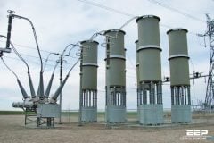
- Cable Sealing End or Cable Head
- Lightning Rod
- Reactor
- BONUS! Download Electrical Transmission and Distribution Reference Book (PDF)
1. Space Heater
A “heater” typically refers to a device designed to generate heat. These heaters are commonly used for temperature control purposes within electrical enclosures or panels. The primary function of installing a heater in an electrical panel is to prevent the temperature inside the panel from dropping too low, especially in environments where low temperatures could lead to condensation or other undesirable effects.
Preventing Condensation: When the temperature inside an electrical panel drops below the dew point, condensation can occur. Condensation may lead to the accumulation of moisture on sensitive electronic components, potentially causing malfunctions or even electrical failures.
Cold Weather Protection: In outdoor installations or locations with cold climates, low temperatures can be a concern. Heaters are used to ensure that the electrical components within the panel remain within their specified temperature range, even during extreme cold conditions.
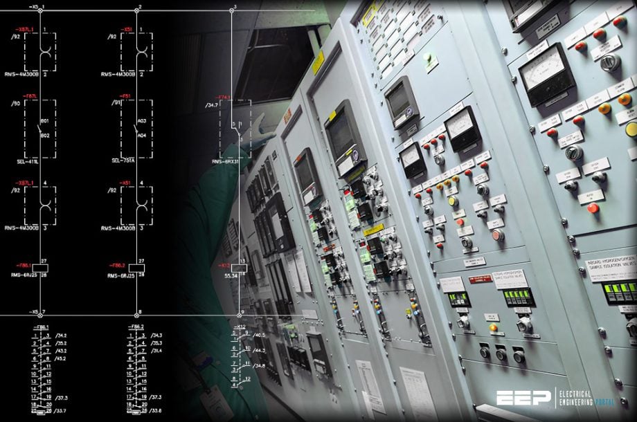
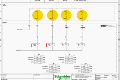
Figure 1 – Space heater controlled by the temperature and humidity sensor
2. Humidity and Temperature Sensor
A Humidity and Temperature Sensor is a device that measures both the relative humidity and temperature of the surrounding environment. The humidity sensor component in the device measures the relative humidity, which is the amount of moisture present in the air compared to the maximum amount the air could hold at a specific temperature.
Relative humidity is expressed as a percentage. The sensor typically utilizes materials that change their electrical properties based on moisture levels. The temperature sensor component measures the ambient temperature of the environment. These sensors are commonly used in all the protection and control panel.
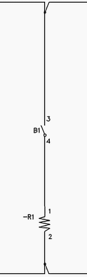
Refer to Figure below showing the temperature and humidity sensor installed in the panel, -B1 is the device name and power supply is connected to terminal 1 & 2, whereas 3 & 4 are the output contact of sensor. When temperature fall below or humidity increases output contact of B1 closes and heater is switched on.
Figure 2 – Temperature and humidity sensor representation in drawings
3. Indication Light
Indication lamps in a control and protection panel provide visual feedback to operators, maintenance personnel, or anyone monitoring the system. These lamps, also known as indicator lights or signal lamps, are used to convey important information about the status and condition of various components within the panel. Indicator lamps are often used to show whether the panel is receiving power.
A green lamp may indicate that power is on, while a red lamp may signal a power failure or shutdown. Lamps can indicate the status of individual circuits within the panel. For example, a green lamp may indicate a closed circuit, while a red lamp may indicate an open or tripped circuit.
The color, type (steady or flashing), and location of the indication lamps are carefully chosen to provide clear and intuitive information. The use of indication lamps enhances safety, allows for quick troubleshooting, and facilitates effective monitoring of the control and protection panel.
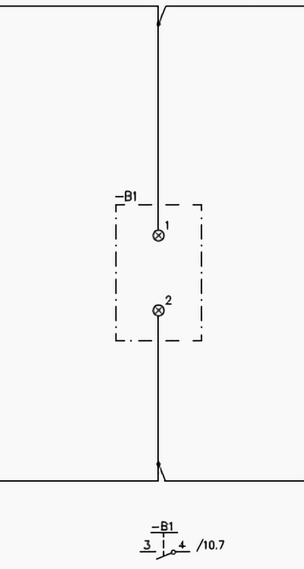
Figure 3 – Representation of lamp in the schematics
4. Test Block
In electrical schematics, a “test block” typically refers to a terminal block or a set of terminals specifically designated for testing and diagnostic purposes. A test block provides convenient access points for measurements, troubleshooting, and verifying the electrical parameters within a circuit.
It is often included in the design of electrical panels or systems to facilitate maintenance and testing activities.
Related electrical guides & articles


Muhammad Kashif
Muhammad Kashif Shamshad is an Electrical Engineer and has more than 17 years of experience in operation & maintenance, erection, testing project management, consultancy, supervision, and commissioning of Power Plant, GIS, and AIS high voltage substations ranging up to 500 kV HVAC & ±660kV HVDC more than ten years experience is with Siemens Saudi Arabia.Profile: Muhammad Kashif
