
Estimated Study Time: 32 minutes
Energy Crisis and Nuclear Power Plants
Energy resources are the backbone of every country in the world. As we are currently witnessing the beginning of the world’s biggest energy crisis in the last 80 years, I believe that every country is now reviewing its energy capacities in case of certain abnormal situations (war or near-war).
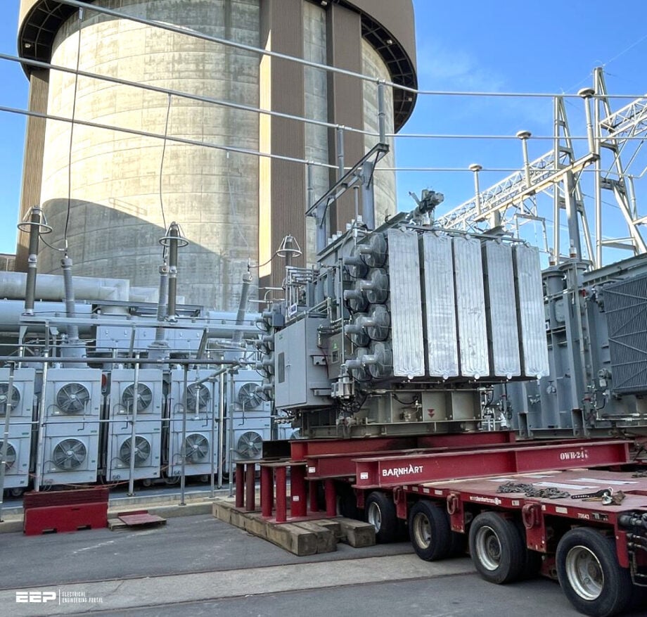 Connecting a Nuclear Power Plant (NPP) to the Grid: Design Issues and Warnings (photo credit: Constellation via Linkedin)
As it seems that so far, the “green” energy plants are, in terms of efficiency, more or less not enough, many countries are thinking about nuclear power plants as a more stable alternative to ensure energy security during crises, especially given the increasing demand for reliable energy sources in the face of geopolitical tensions.
This technical article goes into details of issues and warnings in connecting a Nuclear Power Plant (NPP) to the power grid.
For a nuclear power plant (NPP) to operate safely and economically, it must be connected to an electrical grid system with sufficient capacity to export the NPP’s power and to supply a steady electrical supply to the NPP for safe startup, operation, and regular or emergency shutdown.
Any large new power plant’s connection to a nation’s electrical grid system may necessitate considerable strengthening and modification of the grid system; however, NPPs may require additional requirements to the grid system’s structure and control and maintenance procedures to guarantee sufficient reliability.
Long before the nuclear power plant is constructed, the organization that is responsible for the grid system and the organization that is responsible for the nuclear power plant will need to develop and agree upon the required characteristics of both the grid and the nuclear power plant in order to ensure that they are compatible with one another.
Standard nuclear power plant designs are notoriously huge, which is a major concern, as are the NPP’s unique needs in terms of nuclear safety and a steady power supply.
In addition to the same factors that would be considered when connecting a large fossil fuel or hydroelectric power station to the grid, there are additional considerations when connecting an NPP to the grid.
Based on the size and location of the new nuclear power plant, even a country that now uses nuclear electricity could have to spend a lot of money to upgrade and expand its electric system.
Ok, let’s get into the details!
- Energy Generation-Demand Balance
- Calculation of the Reliability of the Off-site Power
- Requirements of The NPP for Two Independent Connections
- Generator Transformer Design and Sizing
- Unit Transformer Design and Sizing
- Station Transformer Design and Sizing
- Generator Design and Sizing
- Video Course 🎥 Electrical Power Generation Course: Power Plants
- Attachment (PDF) 🔗 Modern Protective Relaying Techniques for Power Transformers and Electromagnetic Transient Analysis
1. Energy Generation-Demand Balance
Requirements of Transmission System Operator (TSO)
The planning and operation of the transmission system is the responsibility of the Transmission System Operator (TSO). The TSO must think about the generation-demand balance in the short-, medium-, and long-term and whether or not the grid needs to be expanded or developed to accommodate adjustments to the demand and generation.
In order for the TSO to conduct the required grid system studies, the design engineer of the NPP must supply all the data needed for these power system studies. A plethora of electrical parameters and the nuclear unit’s size (in MW) will be part of this data.
The technical features or performance standards that the nuclear unit must have in order to satisfy the demands of the transmission system must also be specified by the TSO.
The country’s energy or market regulator may force the TSO to apply the same technical standards to nuclear units as to conventional producers in cases where the electricity market has been deregulated.
Figure 1 – Schematic representation of the different parts of the electrical power supplies for a nuclear power plant
The Transmission System Operator (TSO) will normally require that:
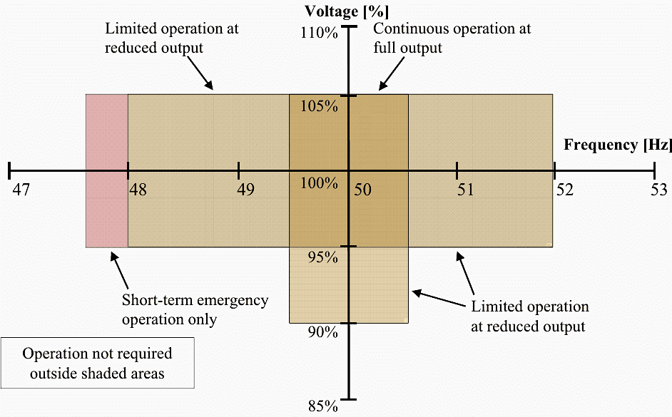
- A generating unit is capable of operating continuously at full output within the typical range of variation in grid voltage and frequency (e.g., +/–5% in voltage, +/–1% in frequency) as illustrated in Figure 2.
- A generating unit is capable of operating for a limited period, on a few situations per year, at a reduced output, for a voltage and frequency range that is outside the normal range (e.g., –10% in voltage and +4%, –5% in frequency), as illustrated in Figure 2.
- A generator has the “fault ride-through” capability, which enables it to continue in operation (i.e., not trip) during specified transient events on the transmission system.For example, the transient voltage dip that occurs when a short circuit fault occurs as a result of a lightning strike on the transmission system in close proximity to the power plant.
- A generating unit is capable of supplying a specific range of reactive power to assist in the regulation of system voltage.
- A generating unit is capable of maintaining operation with a specified level of phase imbalance (negative phase sequence voltage) or harmonic distortion of the voltage waveform.
The Transmission System Operator (TSO) may also require that:
- A generator is capable of operating continuously at any point between maximum load and a specified minimum load, 50% of the entire load, for instance;
- A generating unit is capable to increase or decrease output at a specified rate when instructed. (i.e. to be able to load follow);
- A generating unit features with a speed governor that possesses a specific performance characteristic and is capable of operating in the mode of an automatic frequency control.
- A generating unit comes with a generator excitation control system that has specific performance characteristics, such as the ability to stabilize power and voltage oscillations.
- A generating unit has at least a specified value of inertia or simulated inertia.
The TSO must reach an agreement with the NPP operator regarding the specifics of the grid connections to the proposed NPP, encompassing the quantity of connections and the architecture of the high voltage substation, in order to fulfill the security standards for grid connections mandated by the NPP.
Figure 2 – Depiction of critical frequency and voltage ranges for functionality
2. Calculation of the Reliability of the Off-site Power
Loss of Off-site Power (LOOP)
Predicting the off-site power’s reliability is something the NPP design enfineer must take care of. The pre-construction safety report’s probabilistic safety evaluation will require the grid reliability data. Usually, the TSO would be the one to do this calculation, but in this case, the NPP design engineer would have to outline which power system studies are required.
Using past data on grid faults and occurrences involving loss of grid connection is necessary for calculating the reliability of offsite electricity.
Also needed is a preliminary plan for the future NPP’s connecting strategy. Loss of Off-site Power (LOOP) can have many causes, and it would be helpful to know which ones are most common so that we can take steps to fix them and lessen the possibility of their happening.
Some faults may directly disconnect load or generation. Generating units may also trip off because of a fault within the power plant unrelated to the grid system.
Numerous factors can lead to grid failures, including:
- Strong winds, tornadoes, freezing rain, excessive snow, ice, lightning, and other extreme weather conditions;
- Environmental effects (pollution on insulators etc.);
- Substation equipment faults (mechanical failure, internal flashover etc.);
- Control or protection faults;
- Human error during maintenance or operation;
- Malicious damage.
The submitted non-site and site-specific data should be studied and summarized; Table 1 exemplifies such a summary. The assessment on offsite power reliability must be sufficiently consistent to support the nuclear plant license application.
Table 1 presents two categories of data: the frequency of occurrences causing loss of off-site power (LOOP) and the risk that reactor transients will result in LOOP. Each event type will be evaluated based on duration and frequency by categorizing the occurrences according to their duration, as indicated in the table.
Table 1 – Example of results of assessment of the grid reliability
| Event | Value | Reasoning |
| Short LOOP (<2 h) | Frequency: 6.0 × 10⁻² per year | The most frequent grid failures, with a short recovery time. |
| Long LOOP (2–4 h) | Frequency: 2.0 × 10⁻³ per year | Usually due to less frequent faults between the plant and the transformer and by line faults due to bad weather in the vicinity of the plant (without destruction of equipment). |
| Very long LOOP (24–192 h) | Frequency: 1.0 × 10⁻⁴ per year | Caused by faults that need exceptional means to be cleared (e.g. destruction of equipment such as collapse of transmission towers or damage from flooding in substations). |
| Conditional LOOP after reactor transient (e.g. after a reactor trip) | Probability: 1.0 × 10⁻³ per event 1/3 short LOOP 2/3 long LOOP |
3. Requirements of The NPP for Two Independent Connections
To ensure a dependable off-site power supply for the nuclear power plant’s safety systems, standard design specifications typically require a minimum of two independent connections between the nuclear unit and the grid. The initial connection facilitates the export of electricity from the nuclear unit’s generator to the primary grid through the generator transformer.
The secondary connection supplies the nuclear unit through the station transformer in the absence of the primary connection.
Certain nuclear units possess several station transformers; certain nuclear units also feature more than one generator, resulting in multiple generator transformers. The connections to the generator transformers and station transformers must be constructed to ensure that a single problem does not incapacitate all connections.
Alternatively, both the generator transformer and the station transformer may be linked to the same substation; nevertheless, appropriate isolation between these connections is essential.
A reliable off-site supply also requires a sufficient number of transmission circuit connections from the local substation or substations to the rest of the transmission system, and measures to ensure the substations and transmission circuits are sufficiently robust to withstand extreme events such as hurricanes, tornados, earthquakes or flooding.
Figure 3 shows a simplified single line diagram of the electrical network of an NPP and its grid connections. The output from the generating unit is fed to the grid via the generator transformer. One or more unit transformers are supplied at generator terminal voltage, and provide the electrical power to the plant auxiliaries for start up and during normal operation.
There is a circuit breaker in the connection to the generator terminals, so that the auxiliaries in the NPP can be supplied from the grid when the generator is shut down, by opening this circuit breaker.
Older NPPs did not generally have a circuit breaker at the generator terminals.
Figure 3 – Electrical connections to two substations
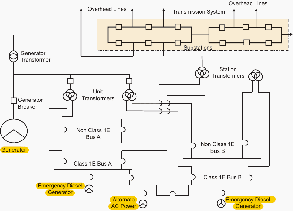
One or more station transformers provide the second connection to the grid and provide an independent supply to the electrical auxiliary equipment.
In this arrangement one station transformer is connected to a different substation from the generator transformer. In this figure the station transformers and unit transformers are each shown as three-winding transformers (with two low voltage windings); some NPP designs use two-winding transformers (with only one low voltage winding).
Figure 4 depicts an alternative arrangement of the connections to the transmission system, where the generator transformer and station transformer are connected to the same substation.
Figure 5 shows yet another arrangement that is to be used for some new large nuclear units. In this case, the unit transformers are connected to the grid voltage alongside the connections to the generator transformer.
Related electrical guides & articles


Edvard Csanyi
Hi, I'm an electrical engineer, programmer and founder of EEP - Electrical Engineering Portal. I worked twelve years at Schneider Electric in the position of technical support for low- and medium-voltage projects and the design of busbar trunking systems.I'm highly specialized in the design of LV/MV switchgear and low-voltage, high-power busbar trunking (<6300A) in substations, commercial buildings and industry facilities. I'm also a professional in AutoCAD programming.
Profile: Edvard Csanyi
